Tele Vue Panoramic Mount User Manual
Panoramic, Mount instructions, Parts check list
32 Elkay Dr., Chester, New York 10918 (845) 469-4551 www.televue.com
Introduction & Use
The alt-azimuth Panoramic
TM
Mount is perfect for our lighter weight scopes and will
work fine with our 4" scopes at moderate powers. It accepts the Sky Tour computer
system as well as the Eyepiece Caddy Set.
The Panoramic Mount Head cradles the telescope at its center of gravity, to make
operation smooth and easy. Brass bearings with tension adjustments provide a
smooth vertical motion from about 17° below the horizon to almost Zenith (85°).
To achieve smoothest operation it is important to have the telescope properly bal-
anced in its mount ring, with the altitude tension knobs providing minimal drag.
The tripod legs are crafted from solid wood and can position the cradle height from
38" to 62". The legs are tied together by either a powder coated cast aluminum
head or solid brass head. The triangular accessory tray adds extra stability to the
tripod.
The Panoramic Mount is ideal for terrestrial and astronomical viewing.
Tripod and Head Set-up
1) Installing Foot Studs
Installing Foot Studs
Installing Foot Studs
Installing Foot Studs
Installing Foot Studs - After removing all packaging material screw the Foot Studs
into the bottom of the Leg Extensions.
2) Installing Leg Extension Lock Knobs
Installing Leg Extension Lock Knobs
Installing Leg Extension Lock Knobs
Installing Leg Extension Lock Knobs
Installing Leg Extension Lock Knobs - Screw Leg Extension Lock Knobs into the
metal Leg Clamp bands.
3a) Setting-up on level ground
Setting-up on level ground
Setting-up on level ground
Setting-up on level ground
Setting-up on level ground - With the tripod upside down, pull the 3 Leg
Extensions to the same height and lock in place with Leg Extension Lock Knobs.
3b) Setting-up on uneven terrain
Setting-up on uneven terrain
Setting-up on uneven terrain
Setting-up on uneven terrain
Setting-up on uneven terrain - Proceed as above, then install Tray (step 4). Extend
remaining legs until head is approximately level. Lock Leg Extension Lock Knobs.
Move on to step 5.
NOTE: The mount only needs to be sufficiently levelled so the telescope swings
smoothly in any azimuth orientation.
4) Installing Tray
Installing Tray
Installing Tray
Installing Tray
Installing Tray - With tripod right side up, spread apart tripod legs. Install Tray
by inserting the stud from one of the hinged Tray Supports through the hole in one
corner of the Tray. Secure Tray using one of the plastic Wing Nuts. (Leave Wing
Nut slightly loose to ease installation of the remaining Tray Support screws.) Mount
Tray on the remaining two supports. Tighten all three Wing Nuts after Tray is in
position.
5) Installing Panoramic Mount Head
Installing Panoramic Mount Head
Installing Panoramic Mount Head
Installing Panoramic Mount Head
Installing Panoramic Mount Head - Set the Panoramic Mount Head into the
Bushing in the Tripod Head. Screw the Lock Knob into the hole in the side of the
Tripod Head and tighten enough so the head cannot be pulled out. Swing the Cradle
until approximately level and tighten the Vertical Tension Knobs. Note
Note
Note
Note
Note: Mount head
can be moved to other Tele Vue tripods or camera tripods by removing the Panoramic
Post. Use 5/64" Allen to loosen lower set screw on Azimuth bearing plate, then
unscrew the post. Normally this set screw is tight to prevent Panoramic Post from
unscrewing from the head as mount is turned in azimuth.
6) Follow instructions packaged with handle to attach it to the mount.
7) Using the Allen wrench provided, screw the studs into the 2 outer holes of the telescope
Mount Ring until they bottom. (Be careful not to overtighten; Mount Ring is aluminum and
threads may strip.)
8) Mounting Telescope
Mounting Telescope
Mounting Telescope
Mounting Telescope
Mounting Telescope - Place the telescope down on the Cradle inserting threaded studs
in the telescope mounting ring into cradle holes. Note, orient telescope so Vertical Tension
Knobs are closer to the telescope's eyepiece end. Fasten in place with plastic Wing Nuts.
9) Loosen Vertical Tension Knobs
Vertical Tension Knobs
Vertical Tension Knobs
Vertical Tension Knobs
Vertical Tension Knobs and balance telescope so that Vertical Tension Knobs
Vertical Tension Knobs
Vertical Tension Knobs
Vertical Tension Knobs
Vertical Tension Knobs
need very little, if any, tightening.
10) Remember
Remember
Remember
Remember
Remember, when carrying with or without telescope, the Mount Head
Mount Head
Mount Head
Mount Head
Mount Head can easily slip
or fall out if the lock knob is loose.
*LEAVE WING NUTS ON STUDS WHEN STORING SCOPE IN CASE
TO PREVENT RIPPING FOAM LINER.
PANORAMIC
TM
MOUNT INSTRUCTIONS
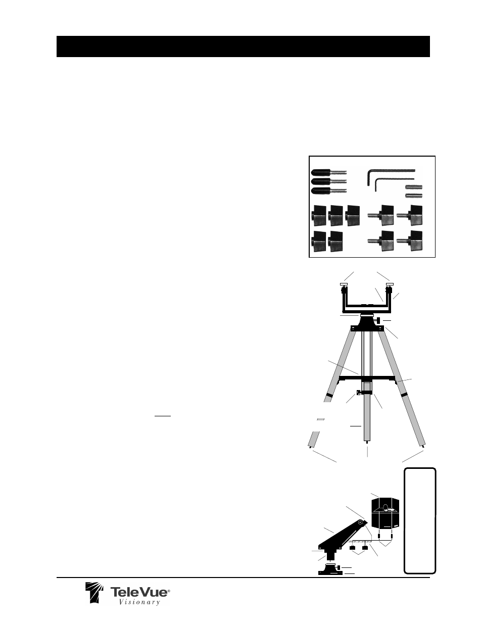
CRADLE
LOCK KNOB
123
123
123
VERTICAL TENSION
KNOBS
TRIPOD HEAD
TRAY
LEG EXTENSION
LEG CLAMP
TRAY
SUPPORT
BUSHING
RUBBER TIPPED STUDS
LEG EXTENSION
LOCK KNOB
PANORAMIC
MOUNT HEAD
LOCK KNOB
WA
RN
IN
G
: Rotating the T
ele-Pod head
w
hile the azimuth tension knob is tight-
ened could cause the azimuth bearing to
unscrew and separate.
WING NUTS
TRIPOD HEAD
PANORAMIC
MOUNT HEAD
VERTICAL
TENSION KNOB
WITH TELESCOPE
OBJECTIVE FACING LEFT
AZIMUTH
BEARING
PLATE
PANORAMIC
POST
CRADLE
STUDS
Rubber tipped studs for tripod legs
Studs for scope attachment
1/8" Allen Key
5/64"
Allen
Key
Plastic Wing Knobs for scope & tray attachments
Leg Extension & Mount head Lock Knobs
Parts Check List
Parts Check List
Parts Check List
Parts Check List
Parts Check List
•Panoramic Mount Head
•Wood Tripod
•Tray
•Mount Handle
•Small-Parts Bag includes:(3) Rubber Tipped
Studs for tripod legs, (2) Studs for scope
attachment, (1) 1/8" Allen Key, (1) 5/64"
Allen Key, (5) Plastic Wing Knobs for scope
and tray attachments, (4) Leg Extension and
Mount head Lock Knobs