Figure 8. mounting the switch on the rack – Allied Telesis AT 8000/8POE User Manual
Page 39
AT-8000/8POE Layer 2 Fast Ethernet Switch Installation Guide
39
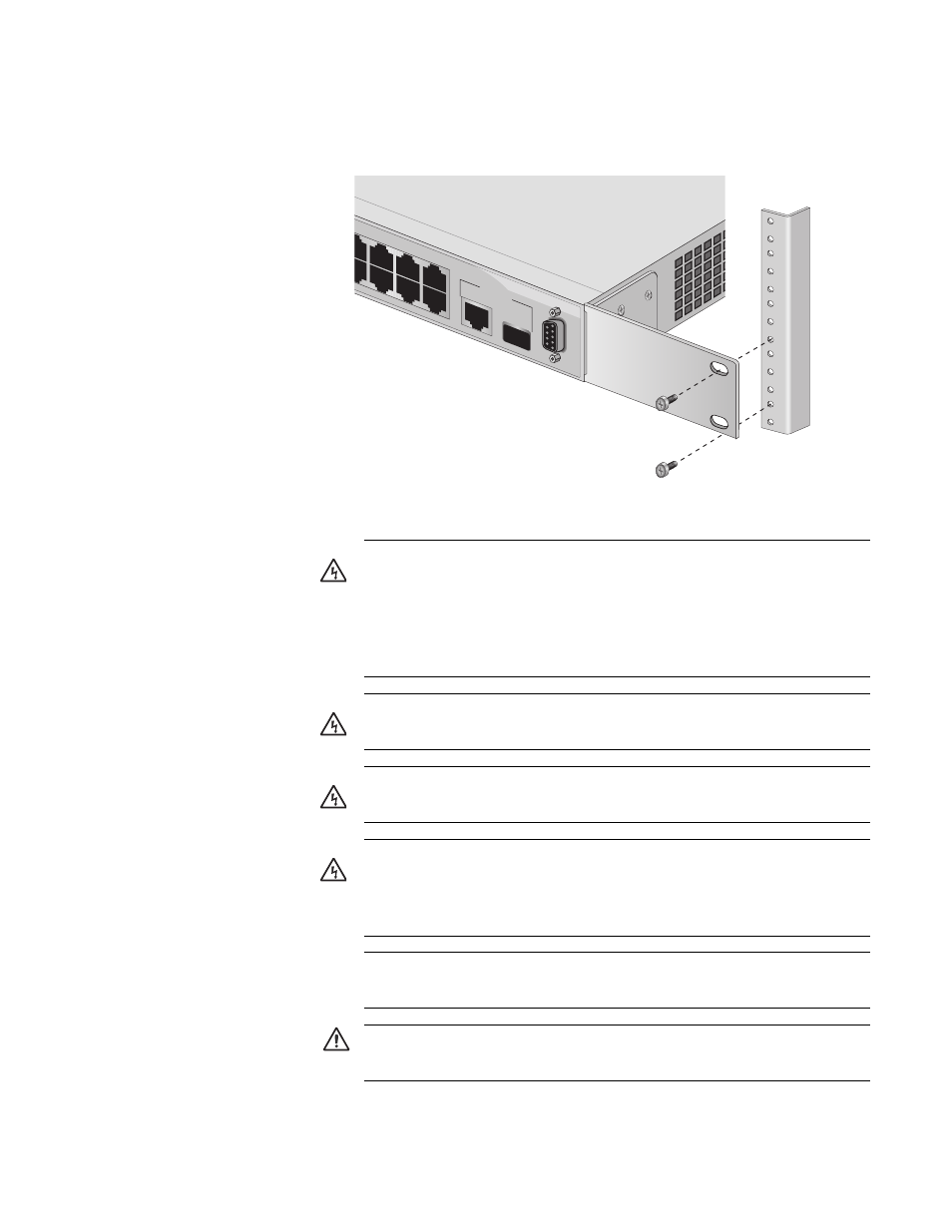
4. Mount the switch on a 19-inch rack using the four large screws
included, as shown in Figure 8
Figure 8. Mounting the Switch on the Rack
9
9R
1
3
5
7
2
4
6
8
TERMINAL POR
T
10/100/1000
Ba
se-T
SFP
UPLI
NK PO
RT
RS-232
832
Warning: To prevent electric shock, do not remove the cover.
No user-serviceable parts inside. This unit contains hazardous
voltages and should only be opened by a trained and qualified
technician. To avoid the possibility of electric shock, disconnect
electric power to the product before connecting or disconnecting
the LAN cables.
E1
Warning: Do not work on equipment or cables during periods of
lightning activity.
E2
Warning: Power cord is used as a disconnection device. To de-
energize equipment, disconnect the power cord.
E3
Warning: Class I Equipment. This equipment must be earthed.
The power plug must be connected to a properly wired earth
ground socket outlet. An improperly wired socket outlet could
place hazardous voltages on accessible metal parts.
E4
Pluggable Equipment. The socket outlet shall be installed near
the equipment and shall be easily accessible.
E5
Caution: Air vents must not be blocked and must have free
access to the room ambient air for cooling.
E6