Leds, Figure 3. port leds, Table 2. 10/100base-t poe port leds – Allied Telesis AT 8000/8POE User Manual
Page 20
Chapter 1: Overview
20
LEDs
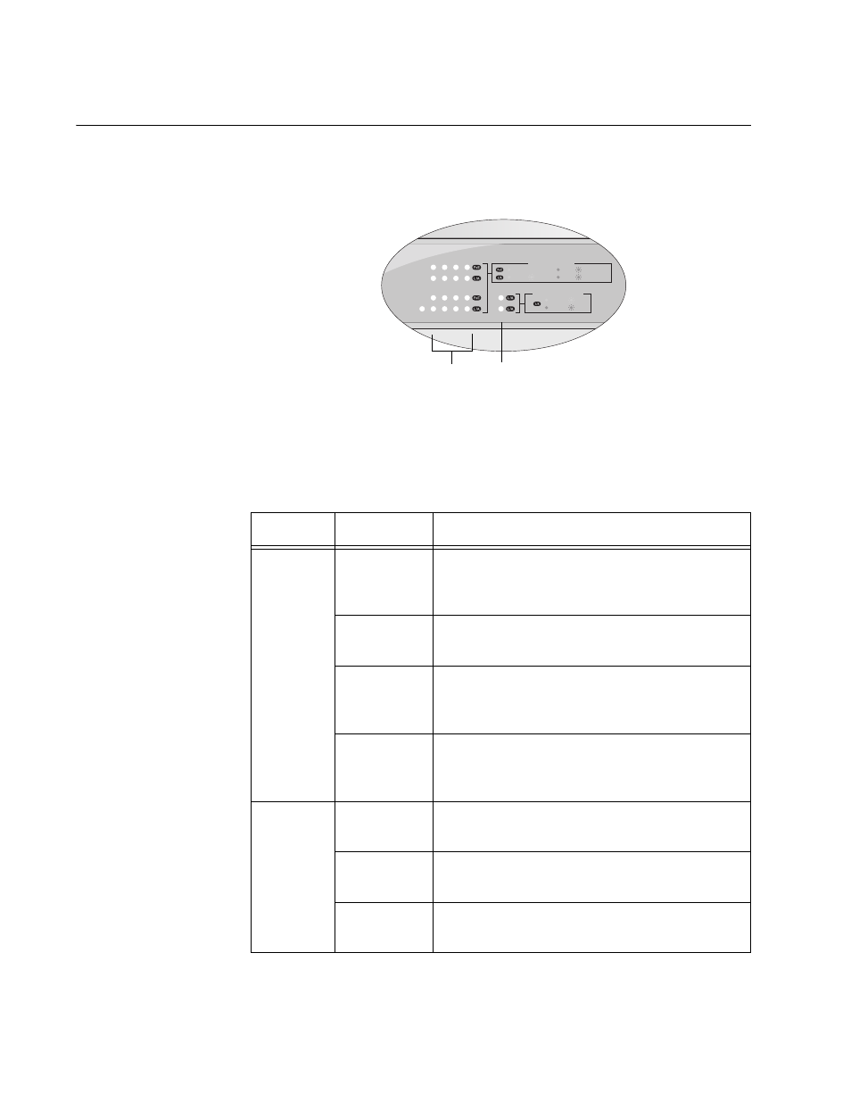
The LEDs on the front panel display the system and port status
information. Each port has two LEDs as shown in Figure 3.
Figure 3. Port LEDs
Table 2 describes the LEDs for the 10/100Base-T ports.
Table 2. 10/100Base-T PoE Port LEDs
LED
State
Description
PoE
Solid green
The port is connected to a valid powered
device and power is being supplied to the
port.
Solid amber The power required by the connected device
exceeds the port’s power budget.
Blinking
amber
The overall power budget for the switch was
exceeded when powered device was
connected to this port.
Off
The port is not connected to a valid powered
device and power is not being supplied on
the port.
LINK/ACT Off
The port has not established a link with an
end node.
Solid green
A valid link has been established on the port
and the port is operating in 100Base-T mode.
Blinking
green
The port is transmitting or receiving data at
100 Mbps.
822
1
3
5
7
2
4
6
8
9
9R
POWER
DET ON ON
100 LINK ACT
10 LINK ACT
PD ON
MAX CURRENT
PD ERR
10/100 LINK
1000 LINK
ACT
ACT
MAIN PORT ACTIVITY
UPLINK PORT ACTIVITY
10/100Base Twisted Pair Port LEDs
Uplink Port LEDs