Star Water Systems HCP05 User Manual
Page 4
6
95 North Oak Street • Kendallville, IN 46755 • © 2014 Star Water Systems. All rights reserved.
7
95 North Oak Street • Kendallville, IN 46755 • © 2014 Star Water Systems. All rights reserved.
TROUBLESHOOTING
Before ANY work with the pump, SHUT OFF the electrical supply and ball valves #1 and #2 to
prevent electrical shock and water damage.
Problem
Cause
Correction
Pump does not start or shuts
down,
No power supply.
Connect the electricity supply.
Incorrect voltage.
Pump is 115 Volt only.
It will not start with 230V supply.
Incorrectly plumbed.
Confirm FIG 1 installation is correct.
Confirm ball valves #1 and #2 are open
in suction and discharge. Confirm ball
valve #3 is closed on bypass.
Blocked inlet
Check if pump suction inlet screen is
blocked. See FIG 5.
Insufficient water supply
Insure water source is providing
sufficient water.
Pump starts when no water is
consumed.
Pipe leaking.
Insure all threads have 3 wraps of
Teflon tape + hand tight + 1/2 turn with
wrench.
Tank pressure is low.
See FIG 3 to check and add air
pressure to the tank.
Air in the system.
Insure all threads have 3 wraps of
teflon tape + hand tight + 1/2 turn with
wrench. Re-prime unit.
Pump does not shut down
when water is not consumed.
Blocked check valve.
See FIG 4. Confirm check valve is free
of debris and functions freely.
MAINTENANCE REqUIREMENTS
• Pressure Tank Charge – should be checked
every 3 months to confirm tank air pressure. See
FIG 3 for description to check air pressure.
Note – tank pressure should be set
approximately 5 psi higher than the expected
incoming pressure.
• Internal Check Valve – if Teflon tape or debris
enters into the pump cavity, the operation of the
internal check valve can be restricted. This may
create an erratic or poor performance with the
pump. To clean the check valve see FIG 4.
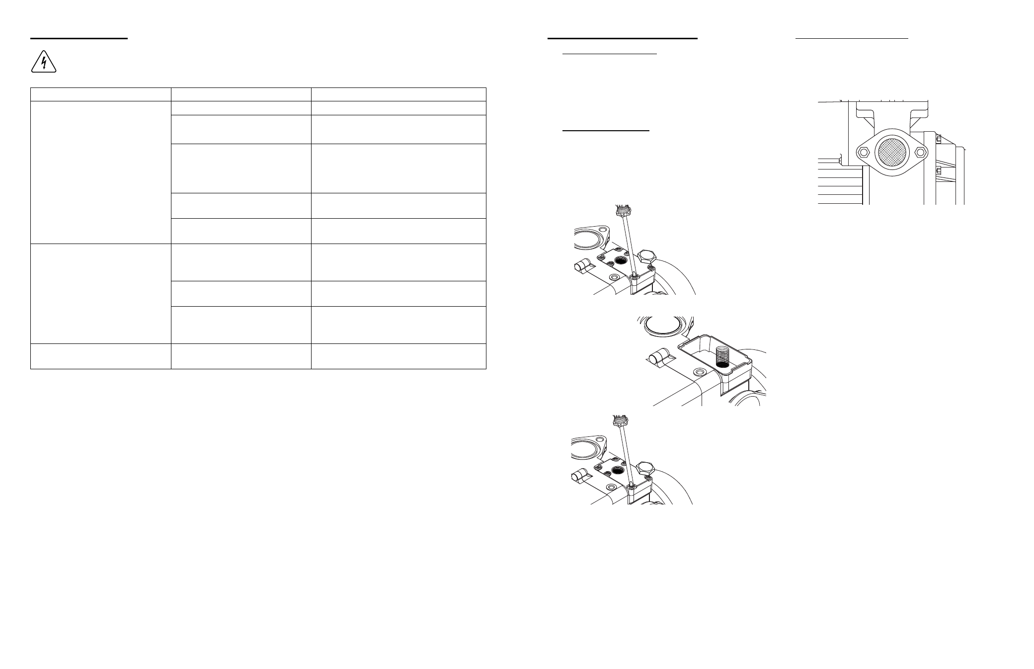
FIG 4 – INTERNAL CHECK vALvE
a. Remove the air relief
port and top cover
b. Confirm the spring
and check valve are
free of debris
a. Reassemble the top
cover and air relief
port
IL1308
• Pump Suction Inlet Screen – if internal debris
blocks or restricts the inlet suction screen (FIG
5), manually clean with hands.
FIG 5 – INLET SCREEN
IL1310