Star Water Systems 3SDHL User Manual
Page 2
2
© 2011. All rights reserved.
11.
CAUTION: Check to be sure your power source
is capable of handling the voltage requirements of the
motor, as indicated on the pump name plate.
12.
CAUTION: The installation of automatic pumps
with variable level float switches or nonautomatic
pumps using auxiliary variable level float switches
is the responsibility of the installing party and care
should be taken that the tethered float switch will not
hang up on the pump apparatus or pit peculiarities
and is secured so that the pump will shut off. It is
recommended to use rigid piping and fittings and the
pit be 18" or larger in diameter.
13.
CAUTION: Information - vent hole purpose.
It is necessary that all submersible sump pumps
capable of handling various sizes of solid waste be of
the bottom intake design to reduce clogging and seal
failures. A check valve with an integral weep hole
is incorporated in the installation to purge the unit of
trapped air (See page 4). Trapped air is caused by
agitation and/or a dry basin. Vent hole should be
checked periodically for clogging. NOTe: THe HOLe
MuST Be CLeANed perIOdICALLY. Water stream
will be visible from this hole during pump run periods.
14.
CAUTION: pump should be checked frequently
for debris and/or build up which may interfere with the
float “on” or “off” position. repair and service should
be performed by Star Water Systems Authorized
Service Station only.
15.
CAUTION: Sump pumps are not designed for
use in pits handling raw sewage.
16.
CAUTION: Maximum operating temperature
for standard model pumps must not exceed 104°F
(40°C).
Note: pumps with the "cCSAus" mark are tested to uL
Standard uL778 & CSA Standard C22.2 No. 108.
GENERAL INFORMATION
The 2N1 system is designed to provide a primary and a
backup sump pumping capabilities. The primary pump
will operate as long as it is receiving AC electrical power.
The AC power is interrupted, the backup sump pump
will begin pumping automatically. The primary pump,
backup pump, electronic controls and all parts required
for installation are included except the battery which is
supplied by the user.
1. The primary pump is equipped with an
omnidirectional mechanical float switch. The pump
will turn on automatically when the water level
in the sump reaches approximately 10.25” and
automatically turn off when the water is pumped
down to 4.125”. The back-up pump is equipped
with a vertical float switch. The pump will turn on
automatically when the water level in the sump
reaches approximately 11” and automatically turn off
when the water is pumped down to 9.25”.
2. The sump pit must be a minimum of 22" deep and
18" in diameter. The pump assembly requires a
minimum diameter of 18" so that the float switches
will operate without restriction. Any smaller diameter
may restrict the switches operation, resulting in pump
failure.
INSTALLATION
1. For your safety, turn off the electrical power at the
service entrance to avoid any possible electrical
shock hazards.
2. On a replacement installation, remove the existing
pump from the sump by disconnecting the discharge
pipe or hose from the old pump. depending on how
your old pump is installed, unscrew clamps and
discard old corrugated hose, or unscrew galvanized
or plastic pipe from pump discharge. If discharge
pipe cannot be removed easily, saw through the pipe
about five feet above the pump discharge.
3. After removing the old pump, remove sediment,
debris, and any standing water from the sump pit.
4. place your pump assembly in the sump and attach
the discharge piping – The pipe must be supported
from above to ensure adequate support for the pump
assembly.
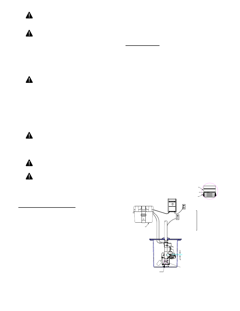
5. Be sure that the pump assembly is positioned so that
the float switches move freely without touching the
wall of the sump or other obstructions. (See Fig. 1)
ensure that the “off” level of the float is 1" min. above
the discharge tee of the dC backup pump (see Fig.
1). Move floats up and down, making sure of free
movement without interference from any obstructions
inside the sump or lid. Very shallow sumps may
require some adjustment to the vertical float to avoid
overfilling or backing up of water into the sump inlet.
IL1007
Battery Box
Check Valve
Weep Hole Provided
Pump
Discharge
Charger
Outlet
Primary
Pump Outlet
Detail “A”
Must be
installed
on two
separate
circuits
IMPORTANT: Off
level of float assembly
must be 1 in. minimum
above center of tee.
1 in. min.
See Detail “A”
FIGURE 1 - DC PUMP PLUMBED IN LINE WITH
SUBMERSIBLE PUMP