Switch wiring, Caution, Figure 2 how breakers are rated – Hired-Hand RS-300 Door: Indicator Switch User Manual
Page 2: Figure 3, Installation, Figure 4 figure 5
RollSeal, INC.
• 1751 Co Road 68 • Bremen, AL 35033 • Phone 256-287-7000 • Fax 256-287-7010
Manual Part No. 4802-5085 rev 9-03 Page
2 of 2
FIGURE 2
HOW BREAKERS ARE RATED
Circuit breakers are rated for a specific current and up to
104°F(40°C) ambient temperature. After 104°F(40°C),
the current handling capability decreases. Refer to
Figure 2.
Example: A 100 Amp circuit breaker will handle 100
Amps up to 104°F. At 122°F(50°C), the
breaker will only handle 90 Amps. At
140°F(60°C), the breaker will only handle 80
Amps.
The temperature inside a breaker box can run as high as
30°F+ or more above the outside temperature.
NOTE: Breaker box temperature measurements will not
be reliable unless the temperature probe is
placed inside the secondary cover, near the top
center area.
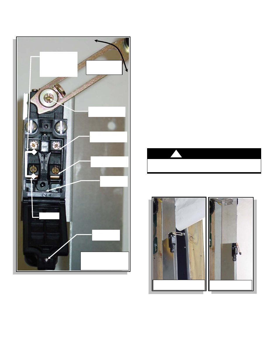
Switch Wiring
FIGURE 3
INSTALLATION
1. Mount the door indicator switch assembly to the RS-
300 door left track using the hardware on the side of
the track as shown in Figure 2. Ensure the assembly
is mounted near the top of the curtain opening while
allowing room for the curtain roller arm operation.
2. Open the wiring access cover and wire the electrical
connections as shown in Figure 3. Tighten the wire
fitting nut securely around the wires.
3. Check all connections to ensure proper wiring and
tightened screws. Close and secure the wiring
access cover.
4. Route the switch wiring safely out of the way and
secure the wires as required.
5. Loosen the Roller Arm Adjustment Screw and
position at a 90 degree angle as shown in Figure 4.
Retighten screw.
CAUTION
The roller arm must be adjusted properly to avoid
damage to the switch assembly and/or curtain.
6. Test the door switch for proper operation when the
door is opened and closed. Refer to Figure 5.
FIGURE 4
FIGURE 5
Wiring Access
Cover Screw
WARNING:
Do Not Open The Access
Cover With Power Applied
To The Switch.
Wiring Access
Hole
OUT – Door Open
(22 N.C.)
OUT – Door Closed
(14 N.O.)
HOT IN
NOTE:
A jumper wire
MUST be placed
from 13 to 21 as
shown.
DOOR
OPEN POSITION
Roller Arm
Adjustment Screw
DOOR
CLOSED POSITION
Roller arm is not
shown in required
mounting position.
!