Hired-Hand PowerTrak: MOTOR & DRIVE ASSEMBLY User Manual
Replacement instructions, Important notice, Directions
Hired-Hand, Inc. • 1733 Co Rd 68 • Bremen, AL 35033 • Phone 256-287-1000 • Fax 256-287-2000
Sheet Part No. 4801-5092 Rev 10-05
Page 1 of 2
Important Notice
This unit is shipped with the UPPER limit knob preset. Installing the Motor & Drive Replacement Assembly requires setting the LOWER
limit knob. The instructions describe how to set the LOWER limit knob. Please follow instructions carefully. UNDER NO
CIRCUMSTANCES SHOULD THE UPPER LIMIT KNOB BE TURNED. This can accidentally occur when setting the lower limit knob.
If necessary, hold the upper limit knob stationary while turning the lower limit knob. Refer to diagram on back of this sheet.
Hired-Hand, Inc. assumes no liability for malfunction or damage of machine caused by improperly setting the lower limit knob.
Tools Required
7/16
″ Socket
3/8
″ Ratchet and extensions
Tape measure
Cable cutters
Small screwdriver
Wire strippers
T-20 torque head driver
Directions
1. Turn on electrical power and run machine to open
vents to their full open positions.
NOTE: When vents are open fully, load block is at
maximum vertical position on drive screw.
2. Disconnect all electrical power sources to
machine. Disconnect controller from machine.
3. Remove cover from machine.
4. Release tension on cables using hand winch.
5. At load block, loosen and remove clamps from cables
(A). Pull cables out of load block and cabinet (B).
6. If distance (C) below access door is 34
″ or greater, do
not remove machine from wall.
7. If distance below access door is less than 34
″, remove
mounting bolts (D). Unhook machine from center
lag mount bolt (E). Place machine horizontal on
board or table.
8. Open access door (F) and disconnect all wiring from
terminal block.
9. Remove and retain Tek screws from bottom cap of
machine (G). Remove bottom cap.
10. Remove and retain bolts from bearing mount (H).
11. Remove and retain motor mount bolts (I) connecting
to cabinet. CAUTION: If machine is vertical, hold
motor assembly while removing motor mount bolts.
12. Carefully slide motor & drive assembly out of
cabinet (J). Completely remove from cabinet.
13. Unscrew load nut/load block assembly from drive
screw of old motor & drive assembly (K).
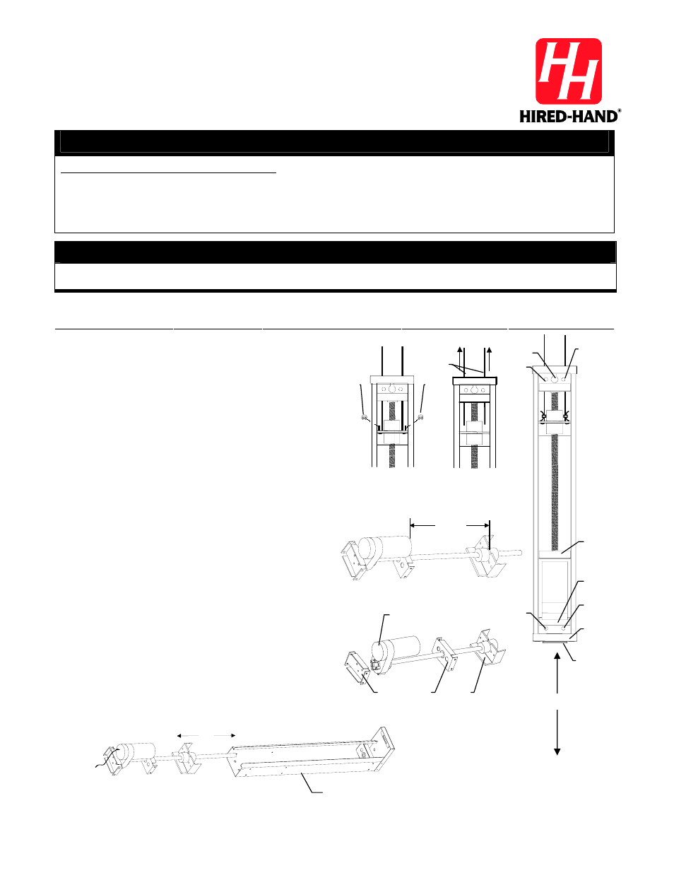
REPLACEMENT INSTRUCTIONS
MOTOR & DRIVE ASSEMBLY
PowerTrak Jr
™
Warning!
Disconnect All Electrical Power Sources To Machine Before Reaching Inside Unit.
J
Cabinet
Distance C must be greater than 34
″ to
enable assembly to be removed. If
distance is less than 34
″, remove
machine from wall and lay machine flat.
18-1/2"
A
B
C
D
D
E
D
D
F
G
I
H
K
L
M
N
A
R