Hired-Hand PowerTrak: Seal Kit Installation User Manual
Page 2
Hired-Hand, Inc.
ã 1733 County Road 68 ã Bremen, AL 35033 ã Phone 256-287-1000 ã Fax 256-287-2000
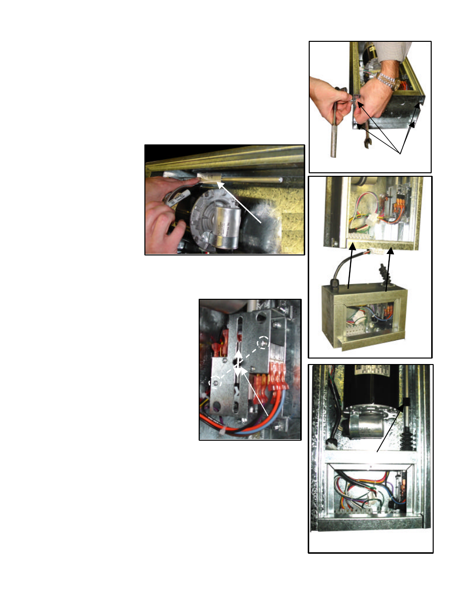
12. Remove the four bolts that hold the bottom plate in place. (Figure 5)
13. Slide out the bottom plate assembly.
14. Slide out the limit switch assembly.
15. Pull wire completely out of the original bottom assembly.
16. Route wire into new assembly through connector provided and
reconnect wire as before.
17. Use the 4” long template provided to measure and mark limit switch
rod. Place
template against
roll pin under
motor mount
plate, mark and
cut rod. Notice
that you may
need to file the
burrs off the end
of rod so that
you can slide rod
into coupling.
See Figure 6.
18. Install new enclosed bottom assembly. See Figure 7. Slide rod and
coupling onto the existing limit switch rod in machine. Tighten
coupling using the 1/8” allen wrench. See Figure 8.
19. After coupling has been tightened
install the four self tapping screws
provided to attach the bottom
assembly to the machine.
20. Align the aluminum cam by drawing
a line between the two screws as
indicated in Figure 9 and setting the
cam in the center position. Tighten
the set screws in the Limit Switch
Assembly.
21. Slide limit switch rod up and down
to be sure that rubber bellows will
extend with the movement of the
rod.
22. Attach the quick connect to mating plug connector to motor.
23. Replace existing PowerTrak door with the new door included with this
kit.
24. Connect power to the PowerTrak.
25. Fully open then close the curtains, vents, or doors connected to the
PowerTrak. Check that the motor turns the right direction, and that
the limit switches are functioning properly. You may have to adjust
the limit switch setting.
Figure 5 Remove Bolts
Template
Figure 6 Cut Rod
Figure 7 Slide In Assembly
New Coupling
Figure 8 Installed Assembly
Figure 9 Limit Switch
Set Screw