Connecting farm hand to two or more powertraks, Out in time r, Out in – Hired-Hand PowerTrak: Three Wire PVR-2 User Manual
Page 2: 2 #1 com var fans lo hi nc, L2 l1 gnd, Com open close com open close, Rhired-hand
Inset A
OUT
IN
Time
r
12
11
10
9
8
7
6
5
4
3
STAGES OUT
12
11
10
9
8
7
6
5
4
3
STAGES
IN
#2
#1
COM
VAR FANS
LO
HI
nc
HH Net
L2
L1
gnd
AC Power
4
3
2
1
SENSOR
S
PowerTrak #1
PowerTrak #2
Closed
Closed
Signa
l
Signa
l
Co
m
Ope
n
Close
Co
m
Ope
n
Close
Pressure
Gnd
Si
g
+12
Aux
Alarm
N.O.
N.C.
R
HIRED-HAND
Inset B
120
VAC
Inset A
PowerTrak #1
Closed
Signal
Com
Open
Close
L2
L1
gnd
AC Power
Inset B
HOT
Inset A
OUT
IN
Timer
12
11
10
9
8
7
6
5
4
3
STAGES OUT
12
11
10
9
8
7
6
5
4
3
STAGES IN
#2
#1
COM
VAR FANS
LO
HI
nc
HH Net
L2
L1
gnd
AC Power
4
3
2
1
SENSORS
PowerTrak #1
PowerTrak #2
Closed
Closed
Signal
Signal
Com
Open
Close
Com
Open
Close
Pressure
Gnd Sig +12
Aux Alarm
N.O.
N.C.
R
HIRED-HAND
Inset B
120
VAC
Inset A
PowerTrak #1
Closed
Signal
Com
Open
Close
120
VAC
120
VAC
L2
L1
gnd
AC Power
Inset B
HOT
GND
OPEN
AC POWER
SIGNAL
CONTROL
NUET
HOT
COM
CLOSE
ACTUATOR
CLOSE
OPEN
COM
1
2
3
4
5
6
7
8
9
GND
OPEN
AC POWER
SIGNAL
CONTROL
NUET
HOT
COM
CLOSE
ACTUATOR
CLOSE
OPEN
COM
1
2
3
4
5
6
7
8
9
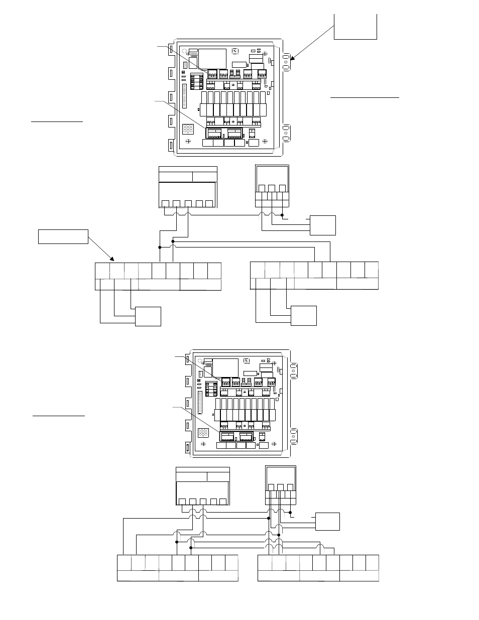
*Connecting Farm Hand to Two or More PowerTraks
Configuration #1
2 Wire Connection
w/ seperate Power Supplies
For Proper Operation:
In this configuration, you must make
sure that the 120 VAC neutral found
at the electromechanical control box
is truly a neutral. Also, the 120 VAC
hot found at the controller must truly
be a hot line.
Configuration #2
4 Wire Connection
w/ Common Power Supply
*Note: If using ground falt intrupt you
must use Configuration 2.
Farm Hand
Controller
3 Wire PVR-2
GND
OPEN
AC POWER
SIGNAL
CONTROL
NUET
HOT
COM
CLOSE
ACTUATOR
CLOSE
OPEN
COM
1
2
3
4
5
6
7
8
9
GND
OPEN
AC POWER
SIGNAL
CONTROL
NUET
HOT
COM
CLOSE
ACTUATOR
CLOSE
OPEN
COM
1
2
3
4
5
6
7
8
9
1