Using the alert alarm iii, 1 the control panel, 2 high limit setpoint – Hired-Hand Emergency Back-Up and Alarms: Alert Alarm III User Manual
Page 4: 3 low limit setpoint, 4 alarm sources display, 5 power on/off, 6 test, 7 sensors, Alert alarm iii, Automatic audible alarm system
Part No. 4801-1201 Rev. 8-99 Alert Alarm III 2
5. Using the Alert Alarm III
5.1 The Control Panel
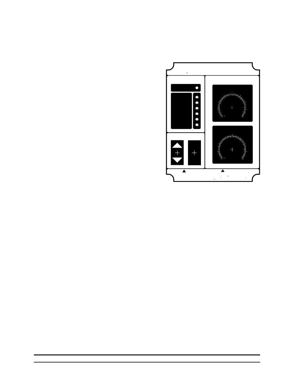
All functions of the Hired-Hand Alert Alarm III
are controlled via the front Control Panel. These
functions include: High Limit Setpoint; Low
Limit Setpoint; Alarm Sources Display; Power
ON/OFF; and Test. The following section
discusses each of these functions in detail.
5.2 High Limit Setpoint
The High Limit Setpoint dial is used to control
the high-side temperature at which the alarm
will sound. This setting is valid for both
temperature sensors. For example: The High
Limit Setpoint is set to 90 degrees. If the
temperature at either or both of the sensors
becomes 90 degrees or more, the Alarm will
sound.
5.3 Low Limit Setpoint
The Low Limit Setpoint dial is used to control
the low-side temperature at which the alarm will
sound. This setting is valid for both temperature
sensors. For example: The Low Limit Setpoint is set to 70 degrees. If the temperature at either or
both of the sensors becomes 70 degrees or less, the Alarm will sound.
5.4 Alarm Sources Display
The Alarm Sources Display consists of the single green and six red lights located at the upper left
of the control Panel. These lights are used to inform the operator at a glance of the status of the
machine. Either conditions are normal, as indicated by the top, green light--or they are not
normal, the Alarm is sounding, and one or more red lights are on to indicate which source(s) have
caused the alarm condition.
5.5 Power ON/OFF
The Power ON/Off switch removes all power from the machine. This includes disconnection the
battery from the circuit board and charger, as well as the AC voltage. Note that the battery will not
charge when the Power switch is OFF.
5.6 Test
The test button provides a means of verifying the operational status of the siren. It is recommended
that the operator press the test button for about 10 seconds at least twice a week. In addition to
ensuring that the alarm is working properly, it helps to condition livestock or poultry to the sound
of the siren--this can be important during hot weather.
5.7 Sensors
The Alert Alarm III comes from the factory with two temperature sensors. It is important to note
that these sensors are fabricated using thermistors and are not interchangeable with sensors that are
commonly used on controllers from other manufacturers. These two sensors may be installed in a
variety of ways. It is recommended that the sensor is high enough from the floor so that livestock
or poultry can not peck at it and it is essential that the sensor not be hung in front of heaters, fans
When this controller is used in a life support heating
and ventilation system where failure could result in loss
or injury, the user should provide adequate backup
ventilation or accept the risk of such loss or injury.
WARNING
ADVERTENCIA
Cuando este control se utilize en sistemas de ventilacion y
calefaccion para seres vivientes donde una falla pueda
causar una perdida o dano, el usuario debera tener sistemas
de ventilacion alternos o aceptar el riesgo de perdida o
danos.
LIMIT SETPOINTS
ALARM SOURCES
TM
ALERT ALARM III
ALERT ALARM III
Automatic Audible Alarm System
HIRED-HAND
R
(PROCEDENCIA DE LA ALARMA)
(LIMITES)
POWER
TEST
(PRUEBA)
(POTENCIA)
Battery Low
Power Out
Sensor 1
Sensor 2
Auxiliary 1
Auxiliary 2
Conditions Normal
(CONDICION NORMAL)
(BATERIA BAJA)
(POTENCIA APAGADA)
(SENSOR 1)
(SENSOR 2)
(AUXILIAR 1)
(AUXILIAR 2)
LOW LIMIT
40
45
50
55
60
65
70
75
80
10
20
5
25
C
F
15
(LIMITE BAJO)
HIGH LIMIT
80
85
90
95
100
105
110
115
120
30
40
45
50
C
F
35
(LIMITE ALTO)
(PRENDIDO)
(APAGADO)
On
Off
R
R