Hired-Hand Emergency Back-Up and Alarms: S-3 Power Switch Upgrade Kit User Manual
Installation instructions, S-3 power switch upgrade kit, Warning
INSTALLATION INSTRUCTIONS
S-3 Power Switch Upgrade Kit
HIRED-HAND MFG., INC. • 1733 County Rd 68 • Bremen, Alabama 35033 · Phone 256-287-1000 • Fax 256-287-2000
Part No. 4802-5104 rev 9-05
Page 1 of 4
WARNING!
Only qualified electrician personnel familiar
with the construction and operation of this
equipment and the hazards involved should
install and/or service this equipment. Read
and understand all instructions and diagrams
before proceeding. Failure to observe this
precaution could result in equipment damage,
severe bodily injury, or loss of life.
/KIT S3 Power Switch upgrade
6450-5092
Tools Required
Small flat-head screwdriver
Tape Measure
Drill
½” Drill Bit
5/8” Wrench
DESCRIPTION
The S-3 Power Switch Upgrade Kit allows previous
models of the Secondary Sensing System without a
power switch to be easily modified to include an
ON/OFF power switch. When common power
connections are used for multiple controllers, the S-3
ON/OFF power switch allows independent power
control. The kit includes the switch, switch spacer nut,
switch boot cover, ON/OFF label, and quick-connect
wire assemblies to connect to existing wire assemblies.
When the kit is received, check for shipping damage or
missing parts. Refer to Table A for kit content.
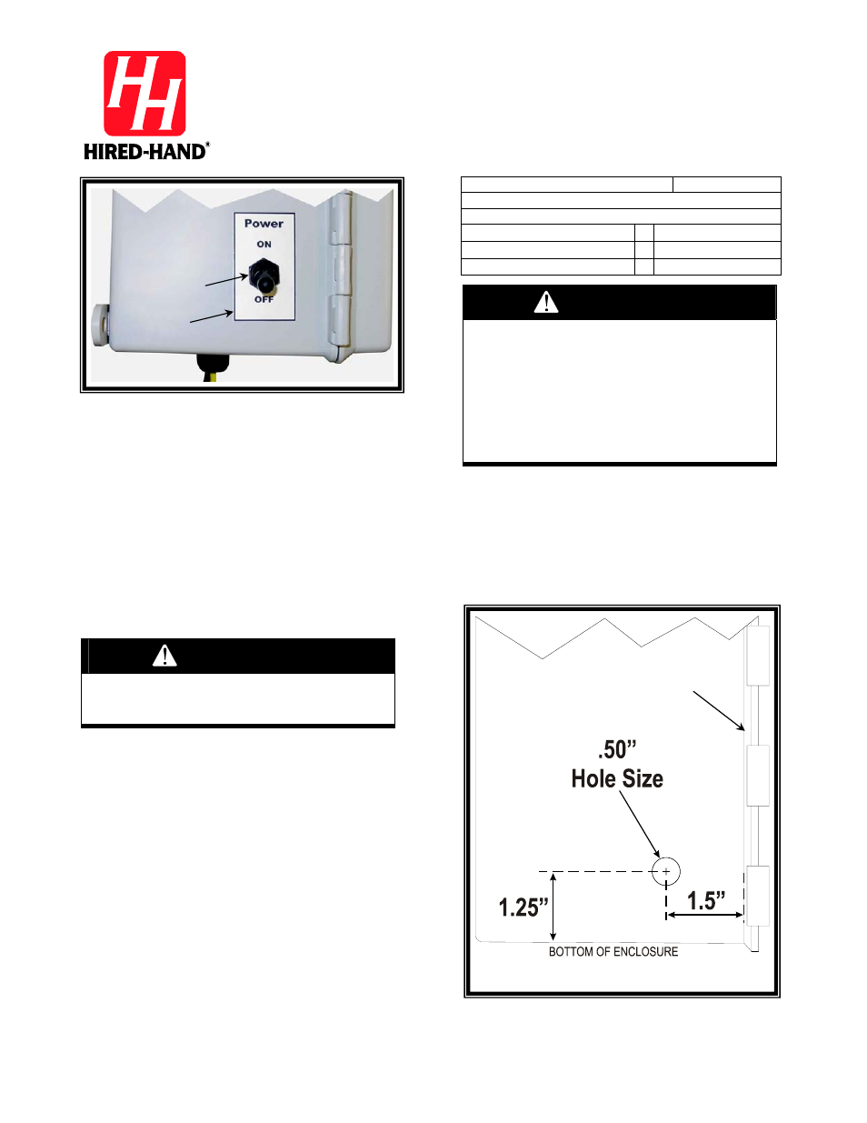
Power Switch Hole Placement
The Power Switch should be located on the hinge side of
the enclosure. The hole must be placed low enough near
the bottom to have clearance from the battery support
bracket.
(1)
Disconnect all AC electrical power from the
Secondary Sensing System controller.
(2)
Disconnect the BAT+ Red wire at the Battery
terminal.
(3)
Use the measurements supplied in Figure 2 and
mark the drill location on the hinge side of the
enclosure.
(4)
Ensure that all wires and other obstructions are
cleared inside the enclosure near the drilling
location.
(5)
Use a ½” drill bit to drill the hole for mounting
the power switch.
(6)
Apply the Power ON/OFF label to the outside of
the enclosure with the label cross-marks over the
center of the drilled hole.
(7)
Cut a hole in the label around the cross-marks to
match the drilled hole size.
Figure 1: S-3 ON/OFF Switch Installed
Bottom
Door Hinge Side
Label
Switch Boot
& Switch
WARNING!
Ensure that the Electrical Power Sources
are OFF during installation / wiring.
Figure 2: Hole Location
Door
Hinge