Eh i, Farm hand alert alarm – Hired-Hand Emergency Back-Up and Alarms: CONVERSION INSTRUCTIONS Alert Alarm III to Farm Hand Alert Alarm User Manual
Page 2
Hired-Hand, Inc. • 1733 Co Rd 68 • Bremen, AL 35033 • Phone 256-287-1000 • Fax 256-287-2000
Sheet Part No. 4801-5097 rev 8-02
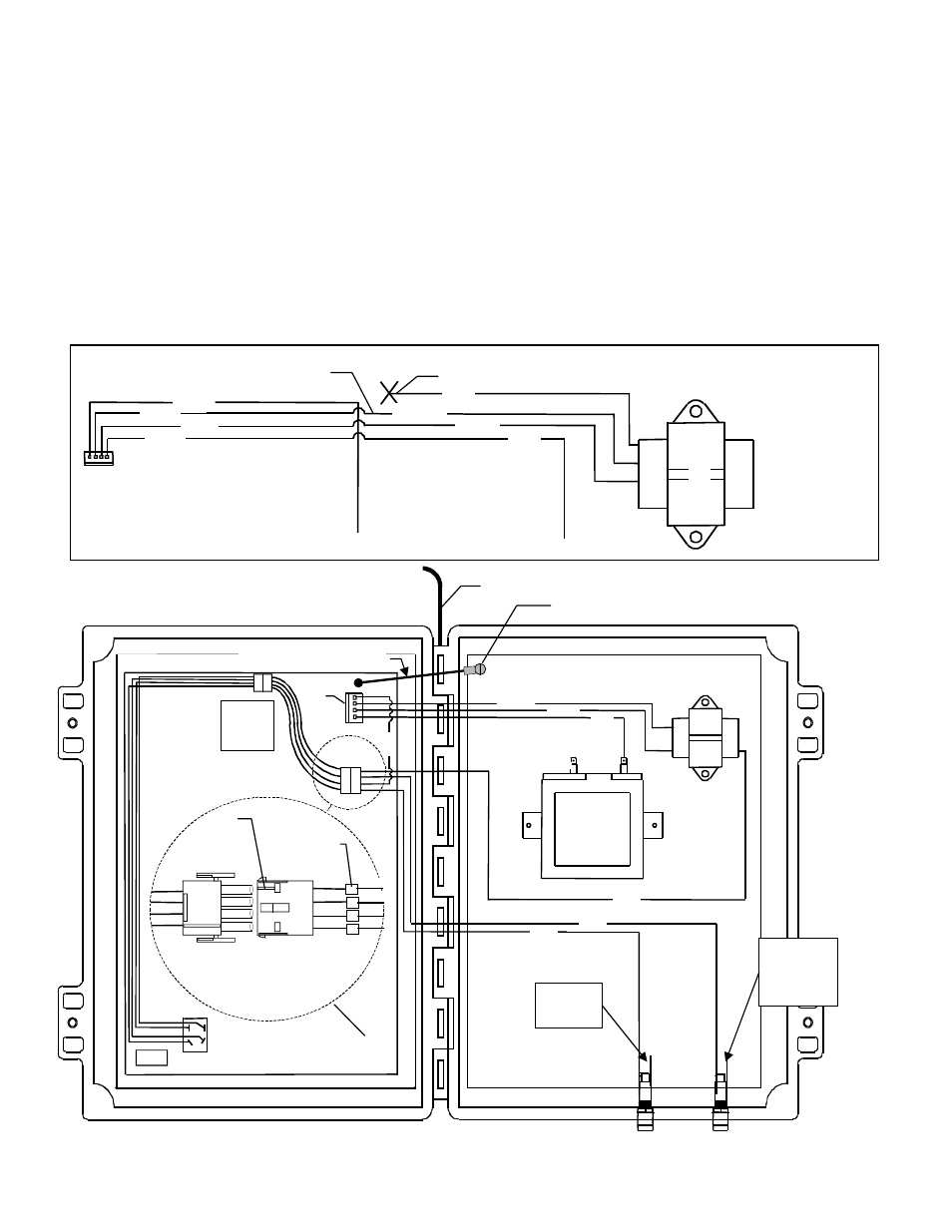
NOTE: Only wires required for installation are shown.
Red
Red
Blk
Blk
Red
Red
Blk
Blk
(4) Blk
(3) Red
(1) Blk
(2) Blk
8. Fit the replacement front cover onto the hinges of the
housing. Insert the metal pin into the hinges (E). This
fastens the new front cover to the housing.
9. Locate the red wire (F) from the transformer that is
connected to a white wire from the 4-pin plug. Cut wire
loose. Cap red wire.
10. Locate the yellow wire from the transformer. Connect
yellow wire (G) to the white wire from the 4-pin plug.
Use wire nut or bell cap to attach wires.
11. Plug the 4-pin connector into the 4-pin terminal (H) at the
top right corner of the electronics board.
12. The power switch is pre-wired with a connector. Refer to
the inset diagram below. Connect the four tagged wires
(that were disconnected from the power switch) to the
open wires leading from the connector (I). Match the
numbers of the tagged wires to the terminal numbers as
shown in the diagram below. Make sure the wire colors
match as shown. NOTE: The connector has a tab
which indicates terminal 1.
13. Attach the Green Ground Wire from the new Door
Assembly to the rear Ground Plate Screw (J).
14. Close and fasten cover
15. Installation completed.
Tran
sforme
r
Red
Yellow
Blue
Blk
Blk
Wht
Wht
Blk
F
G
To Power
Switch
To Bat
tery
E
H
I
Raised Tab
indicates
Terminal 1
FARM HAND ALERT ALARM
Connector shown unplugged
Blk
Yellow
Blk
Blk
Red
Blk
Mated
Connections
Blue
To
Battery
To
Electrical
Outlet
Red
Blk
Replace Red Wire with Yellow Wire.
Green Ground Wire
J