Example circuit, L2 - + l1 in l1 out, Breaker panel lights ev-var pcb 172 – Hired-Hand Evolution Series 3000/3001: Variable Output User Manual
Page 11: Not used, Circuit 1 lights
Part No. 4801-5315 Rev 9-03
Evolution Variable Output
Page 11 of 12
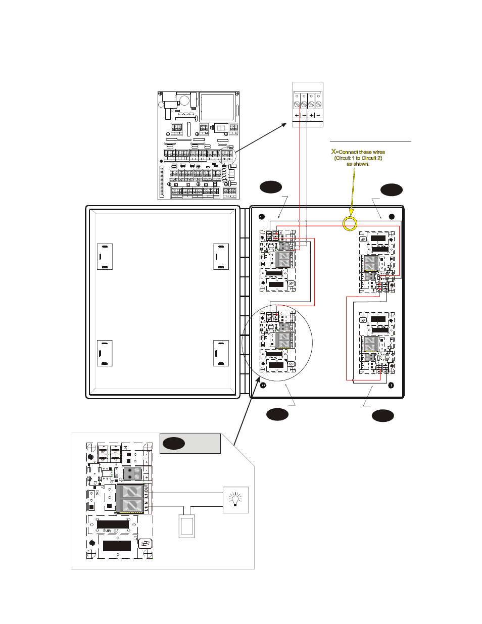
7.4 Combining Circuits to Operate the Same Type of Equipment
In some cases, you may want to operate all lights or all fans. The following is an example of how one would combine circuits one
and three with circuits two and four for only one connection to the Evolution 3000.
CONTROL JUMPERS
AC
V
A
RI
AB
LE
O
U
TP
U
T
EV
O
L
U
T
IO
N
FA
R
M
HA
ND
Hir
ed
Ha
n
d
Co
py
ri
gh
t © 2
0
02
PCB
172
Re
v 01
B. C
rid
er
L2
-
+
L1 IN
L1 OUT
NOT USED
NOT USED
Breaker
Panel
Lights
EV-VAR PCB 172
Close
Aux.
+12V
+12V
Com.
Auxilliary Inputs
Relay Control
Tunnel Aux. Input Vent Aux. Input
Relay Control
Variable Module
HHNet Termination
Power Ventilation Module
Natural Ventilation Module
Var #1
Var #2
Open
U1
Open
U1
Open
U2
Open
U2
Open
AUX
Close
AUX
Open
AUX Com
Close
AUX
Com
Com.
Close
Aux.
Close
U1
Close
U1
Close
U2
Close
U2
+
+
-
-
+12V
GND Shield
Local Network
-
Sensor #1
Te
mper
at
ur
e
S
ens
or
s
Te
m
perature S
en
so
rs
Black
Black
Black
Black
Black
Black
Black
Black
Black
White
Shield
White
Shield
White
Shield
White
Shield
White
Shield
White
Shield
White
Shield
White
Shield
White
Shield
Sensor #2 Sensor #3 Sensor #4 Sensor #5 Sensor #6 Sensor #7 Sensor #8
Outside
N.C.
IN
N.C.
OUT
N.O.
IN
N.O.
OUT
Auxilliary Alarm
DC Power Supply
+12V +5V
11
5 V
23
0 V
AC Supply
L1
L2
Evolution 3000/3001
PCB 169
CONTROL JUMPERS
A
C
V
A
RI
AB
L
E
O
U
T
P
U
T
E
V
O
L
UT
IO
N
F
A
R
M
HA
ND
Hi
re
d
H
a
n
d
C
o
p
y
ri
g
h
t ©
2002
P
C
B
172 R
e
v 01
B
. C
rid
e
r
-
+
EV-VAR PCB 172
CONTROL JUMPERS
AC V
ARIA
B
L
E
O
U
T
P
UT
E
V
O
L
U
T
IO
N
F
A
RM
HA
ND
Hi
re
d
H
a
n
d
C
o
py
ri
ght
© 2
00
2
P
CB 1
72
Re
v
0
1
B.
Cri
d
er
-
+
EV-VAR PCB 172
RE
D
BLK
FACT
O
R
Y
W
IRED
CONN
ECTI
ON
CONTROL JUMPERS
A
C
V
A
R
IA
B
LE
OU
TP
U
T
EV
O
L
U
T
IO
N
FA
R
M
H
AND
Hi
re
d
Ha
n
d
C
o
py
righ
t ©
2
00
2
P
C
B
172 R
ev 01
B.
Cr
id
er
-
+
EV-VAR PCB 172
CONTROL JUMPERS
AC
V
A
RI
ABL
E
O
U
T
P
U
T
EV
O
L
U
T
IO
N
FA
RM
HA
N
D
Hi
re
d
Ha
n
d
Co
p
yr
ig
h
t ©
2
0
02
P
C
B
1
72
R
ev
01
B
. C
rider
-
+
EV-VAR PCB 172
RE
D
BL
K
FA
CT
O
R
Y
W
IRED
CONNE
CTI
O
N
Circuit 1
Lights
RED
BLK
NOTE:
Either “VAR #1” or
“VAR #2” may be
used.
VAR #1
Variable Module
VAR #2
EVOLUTION
PCB 169
EXAMPLE CIRCUIT
Circuit 2
Circuit 3
Circuit 4
(2 kw Max.
@ 120 VAC)
Lights
Connection
Example
Lights
Lights
Lights