Overview, Selecting overloads, Installation tools and parts required – Hired-Hand Contactor Control System (CCS): Triple Pole 16-Stage User Manual
Page 4: Overload control options, Tools required
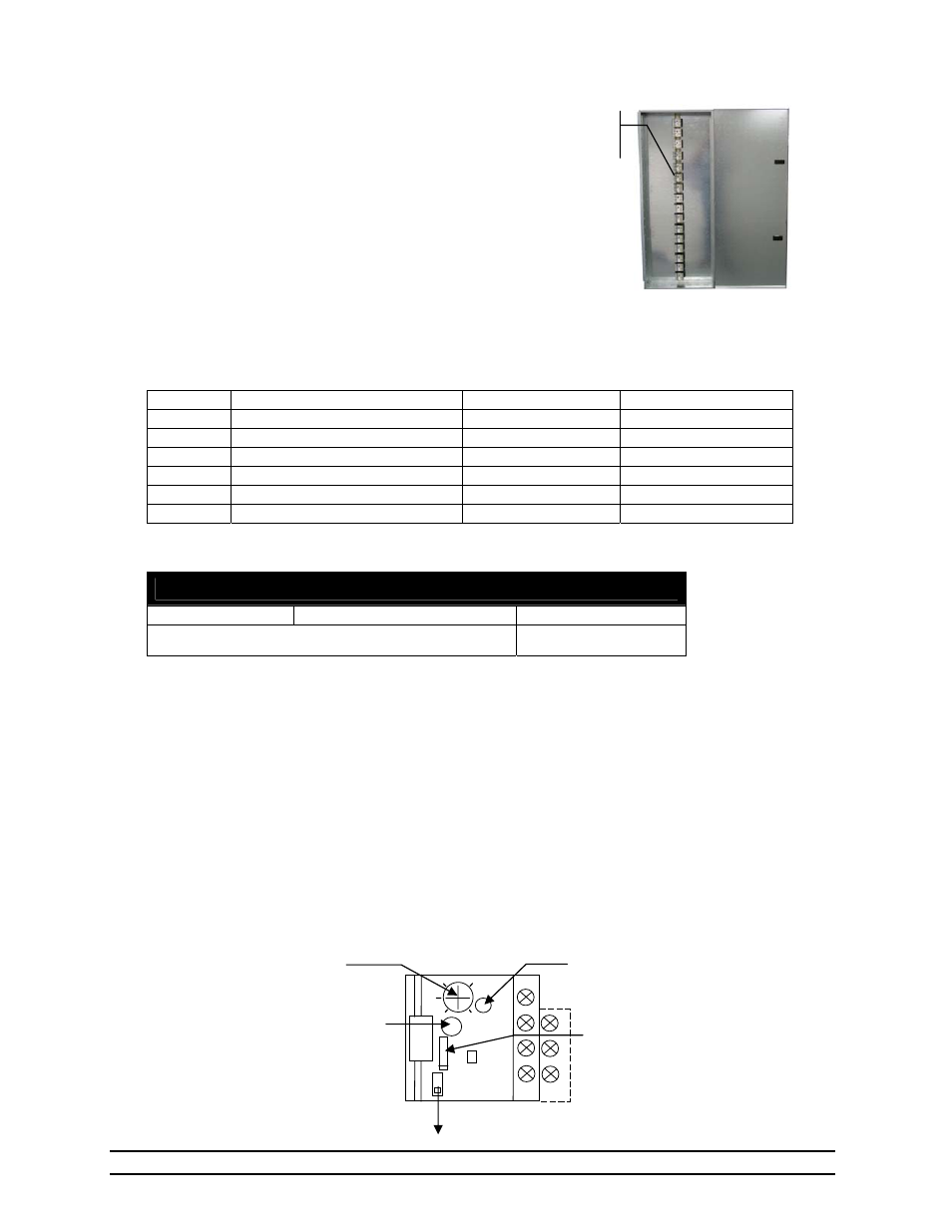
Part No. 4801-5321
Triple Pole 16-Stage Contactor Panel
2
4. Overview
The Triple Pole 16-Stage Contactor Panel
is designed to interface between a Farm
Hand controller and 3 phase load
equipment, however in some cases single
phase loads may be used. Overloads
(thermal relays) are optional equipment for
three phase loads which can be used to
disconnect the power feed between the
contactor and the load whenever a preset
load condition occurs (See Section 5).
5. Selecting Overloads
Overloads are available separately for each stage and sized based upon the Horsepower (HP) and
Overload Part Number. See Section 10 for a listing of the available part numbers The following table
provides examples of stage loads and overload selection.
Stage
Equipment
Total Load
Overload Selection
1
Heater
No Overload
No Overload
2
36” ½ HP Fan @ 220V
½ HP @ 220 V
3015-2895
3
36” ½ HP Fan @ 220 V
½ HP @ 220 V
3015-2895
4
48” 1 HP Fan @ 220 V
1 HP @ 220 V
3015-2892
5
48” 1 HP Fan @ 220V
1 HP @ 220 V
3015-2892
6
Two(2) 48” 1 HP Fans @ 220 V
2 HP @ 220 V
3015-2897
6. Installation Tools and Parts Required
Tools Required
Philips Screwdriver
Flat-Head Screwdriver Wire
Strippers.
Drill and bits needed for mounting hardware
7. Overload Control Options
The Overload control has the following settings:
Overload Current Setting - Set to the desired full load motor current in Amperes.
Press to Reset - Press the blue button to reset the overload after it has tripped.
Automatic/Manual Reset Switch - If set to Automatic (A), the overload will reset itself after a time
delay depending on the thermal cooling of the unit. If an overload condition still exists
the unit will again operate (trip). This setting could result in a cycling mode if the
overload condition is not removed. If set to Manual (H), the unit must be manually reset
before operation can continue after the unit has operated (tripped).
Trip Indicator - The indicator will turn from clear to yellow color when the unit has operated
(tripped).
Test Button - Move the TEST button in the direction indicated to manually operate (trip) the overload
device.
Three Phase 16
Stage Contactor
Panel
Contactors
(16 total)
2.
6
2.
2
1.
8
TEST
LR
2K
96
98
95
97
2 T1
4 T2
6 T3
H A
R
E
SET
Overload current
setting
Move TEST button to operate (trip) the overload
Indicator turns Yellow
when overload has
operated (tripped)
Press to Reset
Automatic/Manual Reset
Switch