Hired-Hand Super-Savers (Forced Air Heaters) XL: White-Rodgers Ignition Control Module User Manual
Page 4
HIRED-HAND, INC.
• 1733 Co Rd 68 • Bremen, AL 35033 • Phone 256-287-1000 • Fax 256-287-2000
Manual Part No. 4802-5086 rev 10-03b Page
4 of 6
NOTE
Ensure the wires are routed and secured away from
hot surfaces.
14. Recheck all wire connections and mounting screws
for accurate connections and screw tightness.
15. Reconnect power and gas to the heater, check for
gas leaks, and test the heater for proper operation.
REPLACEMENT COMPLETED
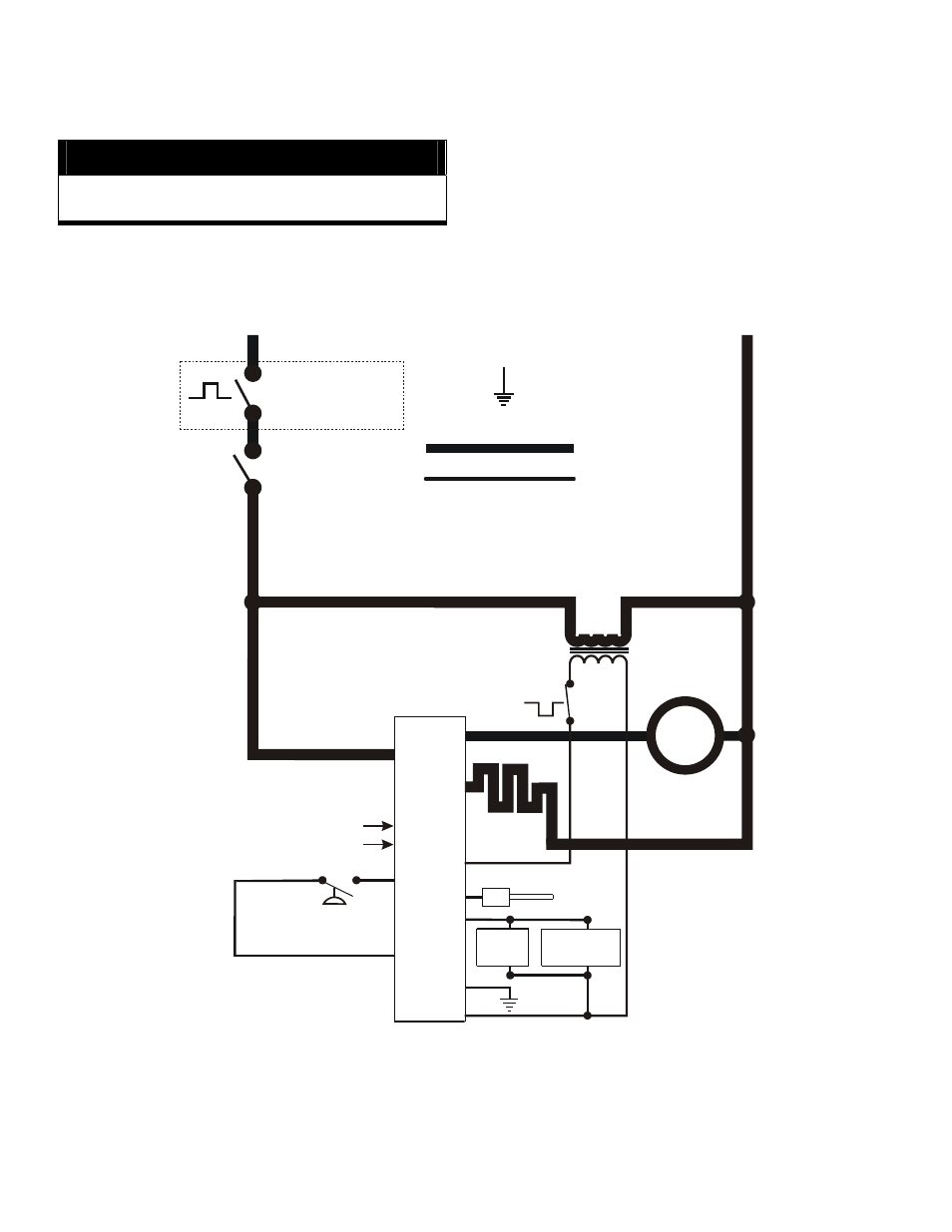
HOT
NEUTRAL
GROUND
LINE VOLTAGE
THERMOSTAT Kit
(Separate External
Cord Set)
ON / OFF
SWITCH
MOT
SILICONE
CARBIDE
IGNITER
GND
REDUNDANT
VALVE
MAIN
VALVE
SAIL SWITCH
IND
LI
HSI
HSIG
L2
PSO
FSG
PSI
W
GV
C
LINE VOLTAGE
LOW LINE
FSI
HIGH LIMIT
SWITCH
BLA
C
K
TRANSFORMER
24 VAC-40VA, 50/60 Hz
WHITE
(Installed on
Later Models)
FLAME
SENSOR
PROBE
(Installed on
Earlier Models)
NOT USED
NOT USED
UNITED
TECHNOLOGIES
Hot Surface
Ignition Control
NOTE: This wiring diagram generically represents several early model heaters after the modifications are performed to
install the UT 1018 Control Module. This wiring diagram does not represent late model heaters which already
have the UT 1018 Control Modules installed.