Warning, Caution, Clean the heater – Hired-Hand Super-Savers (Forced Air Heaters) XL: White-Rodgers Ignition Control Module User Manual
Page 2: Hazardous voltages, Figure 2, Installation, Figure 3
HIRED-HAND, INC.
• 1733 Co Rd 68 • Bremen, AL 35033 • Phone 256-287-1000 • Fax 256-287-2000
Manual Part No. 4802-5086 rev 10-03b Page
2 of 6
CLEAN THE HEATER
Prior to control unit replacement and wire connection,
the heater should be cleaned using compressed air.
WARNING
HAZARDOUS VOLTAGES
Failure To Follow These Instructions May Result in Injury
Or Death!
• The Electrical Connections And Grounding Of The
Appliance Must Be In Compliance With The National
Electrical Code ANSI/NFPA 70. Only A Certified
Electrician Should Perform Electrical Wiring Or
Modifications.
• Do Not Open Doors, Move The Heater, Or Handle
Heater While The Heater Is Hot, Burning, Or
Connected To Power Supply.
• Do Not Clean Or Perform Maintenance Without First
Unplugging The Power Cord And Turning OFF The
Gas Supply.
• Ensure The Power And Gas Remain OFF Until All
Cleaning, Replacement, And Wiring Are Completed
And Verified To Be Safe And Correctly Installed.
FIGURE 2
INSTALLATION
1. Unplug power and turn off the gas supply to the
heater.
2. Lay the new UT 1018 control unit inside the heater
near the old control unit and route the three supplied
new wires from the module side of the heater thru
the back-side to the fan motor side of the heater.
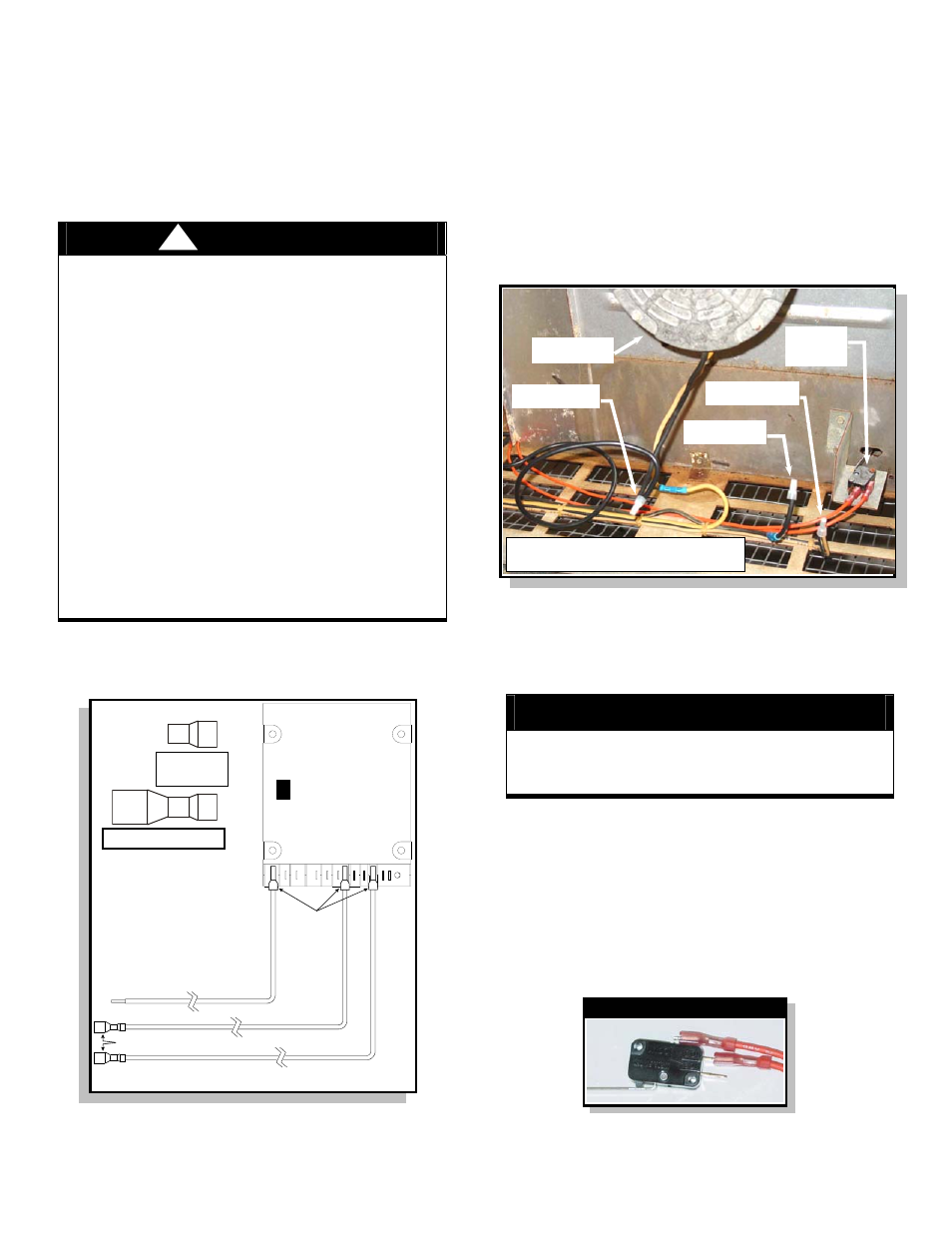
FIGURE 3
3. Cut the Motor’s Black wire approx. 6” from the Motor
and securely crimp a bell-cap connector over the
end of the loose wire. Refer to Connection A.
CAUTION
Ensure the stripped portion of the wires are
completely covered with the crimp connectors and the
connectors are securely crimped.
4. Strip the Motor’s Black wire insulation back ¼” and
twist together to the NEW controller’s “IND” Black
wire. Crimp a bell-cap connector securely over the
two wires. Refer to Connection B.
5. Notice and record which Sail Switch connections are
used then unplug the two wires from the Sail Switch.
Cut the connectors off of both wires, strip both wires
back ¼”, twist the two wires together, and securely
crimp a bell-cap connector over the two wires.
Refer to Connection C.
6. Plug the NEW controller’s “PSI” and “PSO” orange
wires onto the Sail Switch.
Wire Prestripped
0.25”
IN
D
L1
HSI
HSI
G
L2
W
PSI
FSI
GV
PSO
FSG C
NOTE: Three new wire assemblies are supplied.
Other wire connections referenced are reused.
Female Quick-Connect Terminals
Female Quick-Connect Terminals
UT
1018 SERIES HO
T SURF
ACE
IGNITI
ON
!
Sail
Switch
Fan Motor
Figure shown with fan motor and sail
switch wiring modification complete.
Sail Switch Wire Connections
Connection B
Connection A
Connection C
Bell Cap
Connector
Female Connector