Figure 4: assembly & installation of cone – Hired-Hand External Damper Fans User Manual
Page 7
Part No. 4801-5402 Rev. 2/09
Mega-Flow External Damper Fans & Cone Page 7 of 13
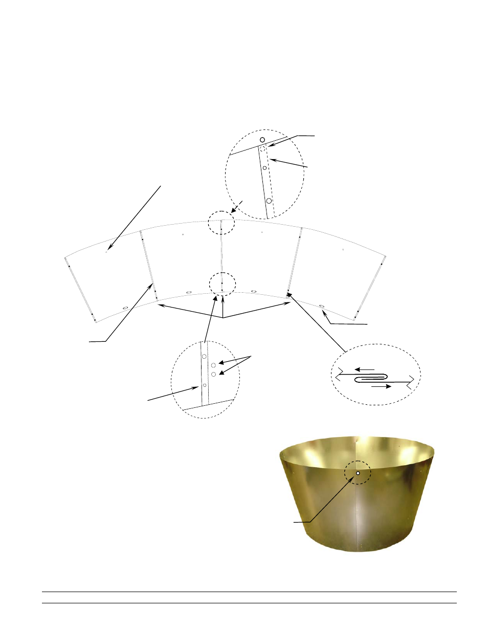
Arrange panels for assembly
with pilot hole on each panel
facing upward.
Slot for mounting top of
cone to fan housing
Joints
Install #14 x 1/2" sm
screw
Install #14 x 1/2" sm
screw
Pilot hole
at top
outside of
cone
Pilot hole faces upward
Pull
flanges
together to
align
mounting
holes
Mounting
Hole for
Wire Guard
9.
Arrange panels contacting as shown in Figure 4. NOTE: The pilot hole pointing upward. Refer to Figure 4
Inset B.
10.
For each panel, slide panels together. See Figure 4 Inset A.
11.
Align holes of flanges. See Figure 4 Inset A. Install sheet metal screws as shown in Insets B and C.
12.
To complete the last flange connection, roll the
cone panels so the small end is on the floor. See
Figure 5. IMPORTANT! The four pilot holes
should be at the top end on the outside of the
cone.
Figure 4: Assembly & Installation of Cone
Mounting Holes for
Damper Ring
Figure 4: Inset A
Figure 4: Inset C
Figure 4:
Inset B
Figure 5: Assembled Cone
- RollSeal Rolling Dampers (5 pages)
- RollSeal Rollup Curtains: Ridder Motor Control (9 pages)
- RollSeal Rollup Curtains: RollSeal Motor Controls (16 pages)
- RollSeal Rollup Curtains: ROLLUP CURTAIN SYSTEM Rev 11-05 (38 pages)
- RollSeal Rollup Curtains: ROLLUP CURTAIN SYSTEM Rev 12-07 (26 pages)
- RollSeal Sidewall System (Curtain): SideWall Curtain (38 pages)
- RollSeal Sidewall System (Curtain): Wiring Diagram And Limit Switches (2 pages)
- RollSeal Sidewall System (Curtain): Floating Hook & Loop Assembly (2 pages)
- Light Traps: Light Trap Fan Unit (2 pages)
- Light Traps: Light Trap Adapter Kit (2 pages)
- Light Traps: 54x54 Light Trap Air Inlet (2 pages)
- Light Traps: 7x44 - 8x44 Light Trap Air Inlet (1 page)
- Light Traps: Light Trap Vent Box Installation (1 page)
- Light Traps: Installing Continuous Light Trap (6 pages)
- Light Traps: Installing Light Trap for Fan (4 pages)
- Light Traps: Light Trap Fan Unassembled (4 pages)
- Baffles, Vents, & Inlets: VENT DOORS Installation (2 pages)
- Baffles, Vents, & Inlets: GRAVITY VENT DOOR Installation (2 pages)
- Baffles, Vents, & Inlets: SINGLE CEILING INLET (2 pages)
- Baffles, Vents, & Inlets: 24 & 36 Chimney Vent (12 pages)
- Baffles, Vents, & Inlets: Vent Kit for Generation Structures (8 pages)
- Baffles, Vents, & Inlets: QUAD CEILING INLET (2 pages)
- Baffles, Vents, & Inlets: Ridge Vent Assembly Instructions (2 pages)
- Baffles, Vents, & Inlets: Installing Ceiling Inlets (2 pages)
- Tunnel Doors (16 pages)
- Circulation and Stir Fans: MEGA-FLOW FANS (See Reverse Side for Framing Formats) (2 pages)
- Circulation and Stir Fans: MEGA-FLOW 24 INCH ORIFICE STIR FANS (2 pages)
- Circulation and Stir Fans: MEGA-FLOW ORIFICE FANS (2 pages)
- Circulation and Stir Fans: Post Mount Assembly For 52 Orifice Fans (4 pages)
- Circulation and Stir Fans: Funnel Flow Fan (1 page)
- Circulation and Stir Fans: MEGA FLOW FANS Round Dairy Fan (2 pages)
- Circulation and Stir Fans: 48 MEGA FLOW (2 pages)
- Circulation and Stir Fans: 48 MEGA FLOW Galvanized (2 pages)
- Circulation and Stir Fans: MEGA FLOW 36 (91 cm) Fan Housing (2 pages)
- Circulation and Stir Fans: 48 MEGA FLOW Fan Housing (2 pages)
- Circulation and Stir Fans: 52 Orifice Fan HSP Conversion Kit (2 pages)
- Circulation and Stir Fans: HAF Fan Mounting Bracket Installation (2 pages)
- Circulation and Stir Fans: POST MOUNT KIT ASSEMBLY (2 pages)
- Circulation and Stir Fans: MEGA FLOW Motor Replacement 36 (91 cm) Fan Housing (2 pages)
- Mega Flow Panel Fans: Econo-Flow 48 Belt Drive Panel Fan (2 pages)
- Mega Flow Panel Fans: Power Cord Installation (2 pages)
- Mega Flow Panel Fans: BELT TENSIONER 48 Mega Flow Fan (1 page)
- Funnel Flow Fans: Belt Tensioner (2 pages)
- Funnel Flow Fans Rev 12-03 (2 pages)
- Funnel Flow Fans Rev 10-98 (1 page)