Warning – Hired-Hand Circulation and Stir Fans: POST MOUNT KIT ASSEMBLY User Manual
Page 2
HIRED-HAND, INC.
•
1733 County Road 68
•
Bremen, AL 35033
•
Phone 256-287-1000
•
Fax 256-287-2000
Manual Part No. 4801-5103
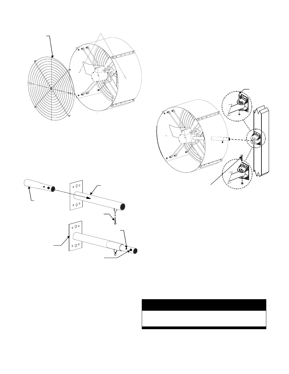
5. Refer to Fig. 3. Insert pivot sleeve inside support
arm as shown. NOTE: Insert smaller diameter end
of pivot sleeve first.
6. Hold support arm pointed downward to allow pivot
sleeve to slide all the way to end of support arm.
NOTE: End of pivot sleeve should protrude from
end of support arm.
7. From inside shroud, insert support arm / pivot sleeve
assembly through saw hole in fan shroud. Opening
for lock bolt on the support arm should be pointed
downward.
8. Fit end plate of the support arm to the inside of the
motor mount bracket. Fig. 4 shows support arm
positioned in motor mount bracket.
9. Securely fasten plate of support arm to motor mount
bracket with 5/16
″
(8 mm) bolts and nuts provided.
10. Replace fan guard.
11. Rotate pivot sleeve with ‘set pin’ hole facing upward.
12. Make sure that protruding end of pivot sleeve is fully
extended from the support arm. Grasp and pull pivot
sleeve to fully extended position, if necessary.
13. Screw lock bolt into threaded lock bolt opening.
Securely tighten lock bolt.
14. Lift fan assembly and insert pivot sleeve between the
flanges of the support bracket (Fig. 4).
15. Align bolt hole in pivot sleeve with the holes in the top
and bottom flanges.
16. Insert bolt through holes in top flange, pivot sleeve, and
bottom flange. Install nut. Tighten bolt & nut to allow
horizontal movement.
17. Rotate fan to desired horizontal angle.
18. Insert set pin through set hole in top flange of support
bracket (See enlarged detail in Fig. 4).
19. Carefully loosen the lock bolt on support arm.
CAUTION: Fan is released when lock bolt is
loosened. Hold fan housing to prevent sudden
movement of fan.
20. Rotate fan to desired tilt angle. Tighten lock bolt.
21. SECURELY TIGHTEN ALL BOLTS AND NUTS AT
THIS POINT OF INSTALLATION.
22. Installation completed.
WARNING!
Failure to tighten all bolts & nuts securely
could result in serious injury.
Pilot holes
Fan guard
Figure 2
Pivot
sleeve
Support arm
Figure 3
Set pin hole
Attachment bolt hole
End plate
Lock bolt
Figure 4
Fan guard not shown
for clarity.
Attachment bolt
Set pin