Hired-Hand Baffles, Vents, & Inlets: Installing Ceiling Inlets User Manual
Page 2
Part No. 4801-0180 Rev 11-08
Installing Ceiling Inlets
Page 2 of 2
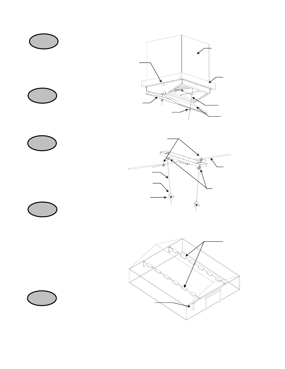
STEP 4
Insert the 1/8” Stainless
Steel rod through the inlet. One rod
will activate the doors simultaneously.
See Figure 3.
Measure 18” for CFM4000
or 11” for CFM2000 from center of
pulleys and fasten the nylon cord to
the 1/8” rod using a 1” cable clamp
(1015-1469). See Figure 4.
STEP 5
Thread the
nylon cord through the
pulley then down through
door. Close the door and
slide the plastic ball onto the
cord. Fasten closed with
azuma nut (1015-4000).
See Figures 3 and Figure 4.
STEP 6
STEP 7
Cut off excess cord leaving 3”.
See Figure 4.
NOTE: The cord will stretch, re-adjust
the azuma nut to keep the door fully
closed.
STEP 8
Installation complete.
Controller
Single Drive
Ceiling Inlet
Figure 3 - Single Rod Assembly
Insulation
Guard
Plastic Ball &
Azuma Nut
Nylon Cord
Door
Rod
Door
Framing Material
Figure 4 - Pulley Assembly
Drive Rod
Nylon Cord
Plastic Ball
(0013-4000)
Azuma Nut
(1015-4000)
Pulley
Cable Clamps
Figure 5 - Single Drive System Layout
- RollSeal Rolling Dampers (5 pages)
- RollSeal Rollup Curtains: Ridder Motor Control (9 pages)
- RollSeal Rollup Curtains: RollSeal Motor Controls (16 pages)
- RollSeal Rollup Curtains: ROLLUP CURTAIN SYSTEM Rev 11-05 (38 pages)
- RollSeal Rollup Curtains: ROLLUP CURTAIN SYSTEM Rev 12-07 (26 pages)
- RollSeal Sidewall System (Curtain): SideWall Curtain (38 pages)
- RollSeal Sidewall System (Curtain): Wiring Diagram And Limit Switches (2 pages)
- RollSeal Sidewall System (Curtain): Floating Hook & Loop Assembly (2 pages)
- Light Traps: Light Trap Fan Unit (2 pages)
- Light Traps: Light Trap Adapter Kit (2 pages)
- Light Traps: 54x54 Light Trap Air Inlet (2 pages)
- Light Traps: 7x44 - 8x44 Light Trap Air Inlet (1 page)
- Light Traps: Light Trap Vent Box Installation (1 page)
- Light Traps: Installing Continuous Light Trap (6 pages)
- Light Traps: Installing Light Trap for Fan (4 pages)
- Light Traps: Light Trap Fan Unassembled (4 pages)
- Baffles, Vents, & Inlets: VENT DOORS Installation (2 pages)
- Baffles, Vents, & Inlets: GRAVITY VENT DOOR Installation (2 pages)
- Baffles, Vents, & Inlets: SINGLE CEILING INLET (2 pages)
- Baffles, Vents, & Inlets: 24 & 36 Chimney Vent (12 pages)
- Baffles, Vents, & Inlets: Vent Kit for Generation Structures (8 pages)
- Baffles, Vents, & Inlets: QUAD CEILING INLET (2 pages)
- Baffles, Vents, & Inlets: Ridge Vent Assembly Instructions (2 pages)
- Tunnel Doors (16 pages)
- Circulation and Stir Fans: MEGA-FLOW FANS (See Reverse Side for Framing Formats) (2 pages)
- Circulation and Stir Fans: MEGA-FLOW 24 INCH ORIFICE STIR FANS (2 pages)
- Circulation and Stir Fans: MEGA-FLOW ORIFICE FANS (2 pages)
- Circulation and Stir Fans: Post Mount Assembly For 52 Orifice Fans (4 pages)
- Circulation and Stir Fans: Funnel Flow Fan (1 page)
- Circulation and Stir Fans: MEGA FLOW FANS Round Dairy Fan (2 pages)
- Circulation and Stir Fans: 48 MEGA FLOW (2 pages)
- Circulation and Stir Fans: 48 MEGA FLOW Galvanized (2 pages)
- Circulation and Stir Fans: MEGA FLOW 36 (91 cm) Fan Housing (2 pages)
- Circulation and Stir Fans: 48 MEGA FLOW Fan Housing (2 pages)
- Circulation and Stir Fans: 52 Orifice Fan HSP Conversion Kit (2 pages)
- Circulation and Stir Fans: HAF Fan Mounting Bracket Installation (2 pages)
- Circulation and Stir Fans: POST MOUNT KIT ASSEMBLY (2 pages)
- Circulation and Stir Fans: MEGA FLOW Motor Replacement 36 (91 cm) Fan Housing (2 pages)
- Mega Flow Panel Fans: Econo-Flow 48 Belt Drive Panel Fan (2 pages)
- Mega Flow Panel Fans: Power Cord Installation (2 pages)
- Mega Flow Panel Fans: BELT TENSIONER 48 Mega Flow Fan (1 page)
- Funnel Flow Fans: Belt Tensioner (2 pages)
- Funnel Flow Fans Rev 12-03 (2 pages)
- Funnel Flow Fans Rev 10-98 (1 page)