Top side, Fan installation, Figure 1 assembled light trap extrusions – Hired-Hand Light Traps: Light Trap Fan Unit User Manual
Page 2: Light trap installation
Top
Side
Figure 2
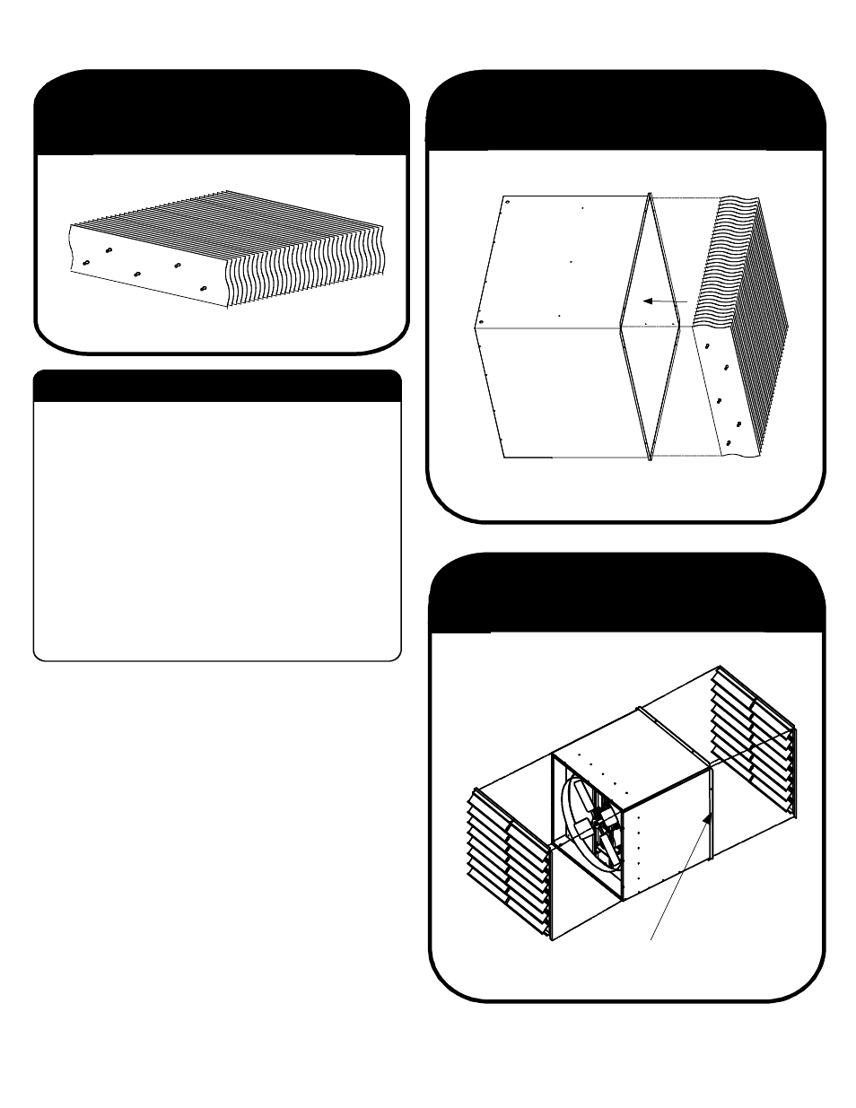
Insert Assembled Extrusions
Into Light Trap Fan Unit
Figure 3
Fan Installation
Fan Installation
1. Cut rough opening in wall. (Minimum dimensions)
a. 48" fans -- 54 3/4" horizontal X 55 3/4" vertical
b. 36" fans -- 42 3/4" horizontal X 43 3/4" vertical
c. 24" fans -- 30 3/4" horizontal X 31 3/4" vertical
2. Place fan through opening, blade end first.
3. Slide fan through opening until the flange is
against the wall. (See Figure 3).
4. Secure fan to wall with wood screws.
5. Install shutter. Shutter can be either
inlet or exhaust.
6. Connect power to fan.
7. Installation complete.
HIRED-HAND, INC.
HIRED-HAND, INC. 1733 Co Rd 68 Bremen, AL 35033 Phone 205-287-1000 Fax 205-287-2000
Manual Part No. 4801-2990
Manual Part No. 4801-2990
LIGHT TRAP INSTALLATION
1.
Assemble the Light Trap Extrusions according to
separate instructions which are included with the
Light Trap Extrusions. See Figure 1.
2
.
Insert the assembled Light Trap Extrusions into the
Light Trap as shown in Figure 2.
Important! Note the orientation of the Light Trap
Extrusions. Make sure to install the
assembled extrusions in the orientation
shown in Figure 2.
3. Slide the Light Trap Extrusions into the assembly until
the stops are encountered.
Figure 1
Assembled Light Trap Extrusions
Flange goes against wall.
Exhaust
Inlet
Shutter