Combined fru replacement in a brocade vdx 6740 – Brocade VDX 6740 Hardware Reference Manual (Supporting VDX 6740, VDX 6740T, and VDX 6740T-1G) User Manual
Page 48
36
Brocade VDX 6740 Hardware Reference Manual
53_1002829_02
Combined FRU replacement in a Brocade VDX 6740
5
You can use external labels as a guide. The combined power supply and fan assemblies are labeled
with an airflow symbol on the faceplate to indicate whether the FRU takes in or exhausts air. The
symbol also appears on the top of the FRU. All FRUs in a chassis must have the same label affixed
so that airflow direction is consistent.
illustrates examples of the airflow labels.
FIGURE 12
Examples of airflow symbols
The green E symbol indicates an exhaust FRU. This unit pulls air in from the port side of the switch
and exhausts it out the non-port side. This is called front-to-back airflow or exhaust airflow. This
symbol should appear on FRUs with part numbers ending with -F.
The orange I symbol indicates an intake FRU. This unit pulls air in from the non-port side of the
switch and exhausts it out the port side. This is called back-to-front airflow or intake airflow. This
symbol should appear on FRUs with part numbers ending with -R.
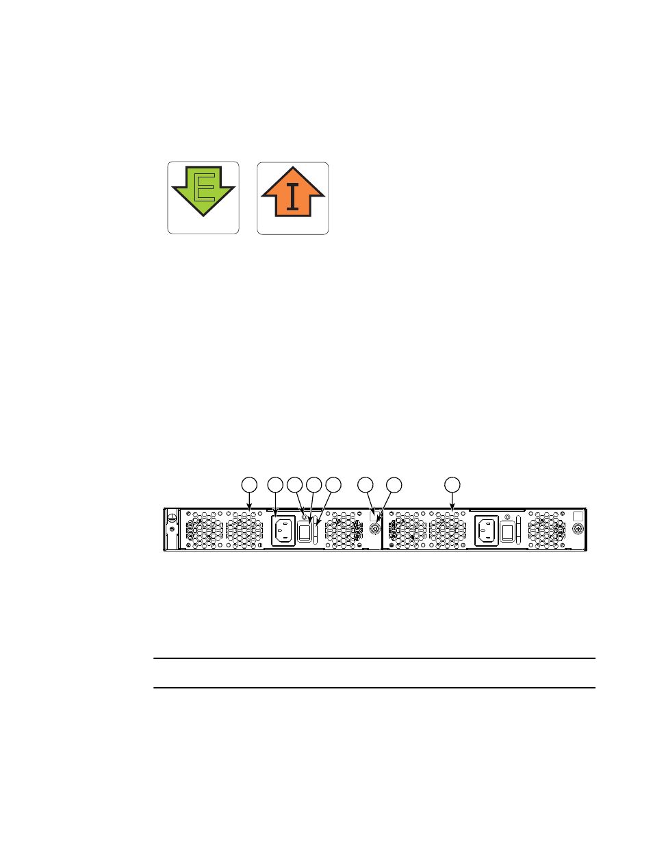
Combined FRU replacement in a Brocade VDX 6740
shows the two combined AC power supply and fan assemblies in the Brocade VDX 6740.
The Network OS identifies the FRUs from left to right as power supply and fan assembly #2 and
power supply and fan assembly #1.
FIGURE 13
Brocade VDX 6740 AC power supply and fan assemblies on the non-port side
ATTENTION
Maintain all power supply and fan assemblies in operational condition to provide redundancy.
AIRFLOW
E
AIRFLOW
1
Power supply and fan assembly #2
5
Handle
2
AC power cord receptacle
6
Airflow label
3
Status LED
7
Captive screw
4
On/off switch
8
Power supply and fan assembly #1
2
3
7
1
5
4
8
6