STI UNIVERSAL STOPPER SERIES User Manual
Page 4
2. If drilling into wood, four #6 x 1 ¼” screws (provided) should be used without anchors and the
mounting holes should be drilled 7/64” diameter to a depth of 1 ¼”. If drilling into masonry or
drywall (sheet rock), the wall anchors (provided) should be used and the mounting holes drilled 3/16”
diameter to a depth of 1 ¼”.
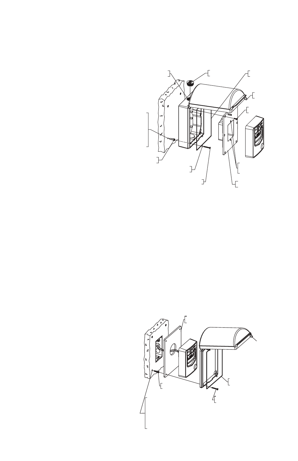
3. Refer to Fig. 2, 3 and 4 for illustrations of the different mounting configurations (BACKBOX,
FLUSH, SURFACE). For additional seal reliability, a silicone sealant may be applied between
optional backplate and wall.
4.
(For the BACKBOX
mounting option only)
If routing conduit from
above, run the conduit
through the hole in the
top of the housing.
5. (For the BACKBOX
mounting option only) If
routing from below, use
a flat head screwdriver
or coin to remove the
NPT Plug. Then knock
out a hole in the bottom
and run the conduit
up through the bottom
of the housing. Apply
thread sealant. Screw
the NPT plug back into
the threaded top of the
housing.
6. (For the SURFACE mounting option only) Note that the inserts fit flush to the housing only in one
orientation (see Fig. 4). Prior to applying either of the Conduit Weather Gaskets, ensure proper
orientation and fit of the desired inserts from the top or the bottom of the housing.
7. (For the SURFACE mounting option only) After noting the proper insert orientation, fit the appropriate
Conduit Weather Gasket size (1/2” or 3/4”) to the conduit. Then fit the gasket to the Conduit Insert or
directly to the housing knock-out. Repeat this step with the appropriate installation on the opposite.
For additional seal reliability, a bead of silicone may be applied to the conduit fitting.
8. (For the SURFACE mounting option only) Use the 3” gaskets (provided) to complete the seal across
the top and bottom insert locations. Overlap 1/8” of the existing Mounting Gasket on the Universal
Stopper body, run the cord into the preformed channel until it overlaps 1/8” of the opposing Mounting
Gasket.
The 3” gasket may need to be trimmed for a proper fit and seal.
9. Align mounting holes in frame to the screw holes made in the wall. If applicable, ensure a proper
seal is made between the wall and
the Mounting Gasket embedded on
the Universal Stopper. If needed, use
optional STI Backplate (STI-1314).
10. (For the BACKBOX mounting option
only) Insert the #6 x 1 ¼” Phillips Pan
Head Screws (provided) into the #6
O-rings STI-01317 (provided) to seal the
Backbox mounting holes.
11. Put the #6 x 1 ¼” Phillips Pan Head
Screws (provided) through the frame
holes into the drilled screw holes and
tighten to mounting surface.
Fig. 2 - BACKBOX MOUNTING OPTION
#6 x 1-1/4 SCREW
(4) PROVIDED
#6 ANCHOR
(4) PROVIDED
3/4 NPT FOR 3/4 CONDUIT
TOP AND BOTTOM
3/4 NPT PLUG
(1) PROVIDED
#6-32 x 1/2 in.
(6) PROVIDED
DRILL 3/16 DIA. HOLES
1-1/4 in. DEEP (4) PLACES
IF ANCHORS ARE USED
DRILL 7/64 DIA. HOLES
1-1/4 in. DEEP (4) PLACES
IF ANCHORS ARE NOT USED
COVER GASKET
(1) PROVIDED
#6-32 x 1/2 in.
(6) PROVIDED
#6 x 1-1/4 in. SCREW
(4) PROVIDED
#6 ANCHOR
(4) PROVIDED
3/4 NPT FOR 3/4 in. CONDUIT
TOP AND BOTTOM
3/4 NPT PLUG
(1) PROVIDED
#6 - 32 x 1/2 in. DEEP
THREADED FOR
MOUNTING DEVICES
DRILL 3/16 DIA. HOLES
1-1/4 in. DEEP (4) PLACES
IF ANCHORS ARE USED
DRILL 7/64 DIA. HOLES
1-1/4 in. DEEP (4) PLACES
IF ANCHORS ARE NOT USED
#6-32 x 1/2 in.
(6) PROVIDED
LOCKING
TAB
O-RING GASKET
(4) PROVIDED
LOCKING TAB
DEVICE MOUNTING PLATE
(1) PROVIDED
O-RING GASKET
(4) PROVIDED
COVER GASKET
(1) PROVIDED
DEVICE MOUNTING PLATE
(1) PROVIDED
#6 - 32 x 1/2 in. DEEP
THREADED FOR
MOUNTING DEVICES
COVER GASKET
(1) PROVIDED
#6 x 1-1/4 in. SCREW
(4) PROVIDED
#6 ANCHOR
(4) PROVIDED
DRILL 3/16 DIA. HOLES
1-1/4 in. DEEP WHEN USING ANCHORS
DRILL 7/64 DIA. HOLES 1-1/4 in. DEEP
WHEN ANCHORS ARE NOT USED
OPTIONAL BACKPLATE RECOMMENDED
WHEN MOUNTING TO UNLEVEL SURFACE
COVER GASKET
(1) PROVIDED
#6 x 1-1/4 in. SCREW
(4) PROVIDED
#6 ANCHOR
(4) PROVIDED
DRILL 3/16 DIA. HOLES
1-1/4 in. DEEP WHEN
USING ANCHORS
DRILL 7/64 DIA. HOLES
1-1/4 in. DEEP WHEN ANCHORS
ARE NOT USED
LOCKING TAB
LOCKING TAB
OPTIONAL BACKPLATE RECOMMENDED
WHEN MOUNTING TO UNLEVEL SURFACE
Fig. 3 - FLUSH MOUNTING OPTION
- 4 -