Lift here, Text here, Important notice – STI UNIVERSAL STOPPER SERIES User Manual
Page 3: Installation instructions, Warranty, Flush end view, Flush side view
Important Notice
(when used on fire systems)
The Universal Stopper is intended to be used in areas where the incidence of false fire alarms from
manual pull stations is high or has proven to be a serious problem. Any disadvantage of this device
is more than balanced when one considers the consequences of false fire alarms, especially if fire
service personnel and equipment are responding to a false fire alarm when they are needed for a real
fire somewhere else. Add to this, the disruption to the facility when false alarms occur. If you have,
or may have, a problem with false fire alarms or physical/weather damage to your fire alarm activation
devices, the Universal Stopper could prove invaluable.
Installation Notes
·
When used outdoors, the manual pull station must also be rated for outdoor use.
·
UL Listing does not permit connection of horn relay contacts to fire alarm or life safety devices.
·
According to UL Listing, models powered from an external power source cannot be supplied from
the fire alarm panel.
· When properly installed, the operation of this cover will not interfere with the function of your life
safety system.
·
Horn operation and performance must be tested annually. Battery replacement is recommended
annually dependent on usage and battery expiration date.
· Ensure the service pin is properly inserted in the service pin receptor to silence horn while
performing installation or servicing horn.
·
If mounting to an uneven surface, a backplate (STI-1314) is recommended to help ensure proper
sealing to mounting surface.
·
The backplate may be drilled if wire access or screw mounting holes are needed.
Installation Instructions
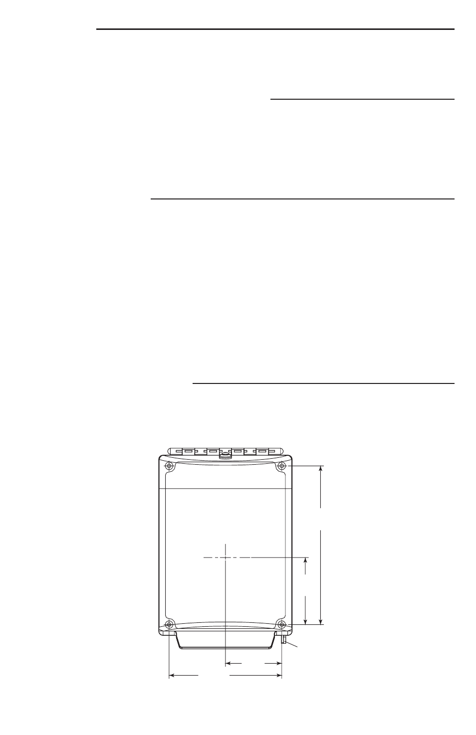
1. Center the pull station to the Universal Stopper with the help of the dimensions in Fig. 1. Open
cover and use the mounting frame or optional backplate to mark the mounting hole locations as
in Fig. 1.
Be sure the entire cover travel will not interfere with operation of the pull station or
other safety system equipment when installed.
4.08 in.
(104mm)
5.42 in.
(138mm)
4.96 in.
(126mm)
4.31 in.
(110mm)
3.25 in.
(83mm)
2.54 in.
(84mm)
2.66 in.
(68mm)
2.0 in.
(51mm)
1.5 in.
(38mm)
1.0 in.
(25mm)
FLUSH END VIEW
.67 in.
(17mm)
5.95 in.
(151mm)WITHOUT HORN
5.28 in.
(134mm)WITH HORN
.42 in.
(11mm)
5.42 in.
(138mm)WITH HORN
6.36 in.
(162mm)WITHOUT HORN
FLUSH SIDE VIEW
LIFT HERE
TEXT HERE
6.45 in.
(164mm)
2.73 in.
(69mm)
2.29 in.
(58mm)
4.58 in.
(116mm)
LIFT HERE
6.45 in.
(164mm)
2.73 in.
(69mm)
2.29 in.
(58mm)
4.58 in.
(116mm)
LIFT HERE
TEXT HERE
6.45 in.
(164mm)
2.73 in.
(69mm)
2.29 in.
(58mm)
4.58 in.
(116mm)
LOCKING
TAB
LOCKING
TAB
LOCKING
TAB
TEXT HERE
Warranty
Three year guarantee against breakage of polycarbonate in normal use (one year on electro
mechanical and electronic components).
Electronic warranty form at www.sti-usa.com/wc14.
- 3 -
Fig. 1