STI SUB-319 User Manual
Installation instructions
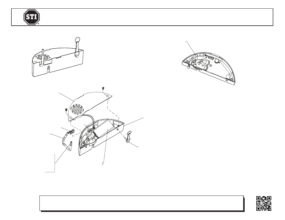
INSTALLATION OF SUB-319 REMOTE WIRING HARNESS FOR STI-6600 SERIES
All specifications and information shown were current as of publication and are subject to change without notice.
SUB-319IS FEB2009
Safety Technology International, Inc.
2306 Airport Road • Waterford, Michigan 48327-1209
Phone: 248-673-9898 • Fax: 248-673-1246
Toll Free: 800-888-4784 • E-mail: [email protected]
Web: www.sti-usa.com
Safety Technology International (Europe) Ltd.
Unit 49G Pipers Road • Park Farm Industrial Estate • Redditch
Worcestershire • B98 0HU • England • Tel: 44 (0) 1527 520 999
Fax: 44 (0) 1527 501 999 • Freephone: 0800 085 1678 (UK only)
E-mail: [email protected] • Web: www.sti-europe.com
POW
RED +
BL
FO
YELL
BL
GR
HORN DEACTIVATION PIN
HORN CASE
ROTATE BATTERY UPWARD
FOR REMOVAL
HORN COVER
HARNESS
WIRE HARNESS COLOR CODE
POWER IN
RED + 12-24VDC
BLACK GROUND
FORM “C” CONTACTS
YELLOW N.O.
BLUE COM
GREEN N.C.
PLUG
JACK
POW
RED +
BL
FO
YELL
BL
GR
ROUTE WIRE HARNESS AS SHOWN
FIG. 3
FIG. 1
INSTALLATION INSTRUCTIONS
1.
Install horn deactivation pin.
2.
Remove horn assembly from clear cover.
3.
Remove 2 screws in horn assembly and remove horn cover (Fig. 1).
4.
Connect wire harness to horn assembly as shown (Fig. 1).
NOTE: The harness plug will only install into jack in one direction.
5.
Route harness wires as shown (Fig. 2).
6.
Reassemble horn cover (Fig. 3).
FIG. 2
NOTE: Form “C” Dry Contact Rating < 30, 1 VAC/DC
Electronic warranty form at www.sti-usa.com/wc14