Renkus-Heinz IC2-FR User Manual
Page 46
Normalize Beam EQ is a new Beamware feature. Selecting this feature by put-
ting a check in the check box instructs Beamware to apply a normalized EQ
curve to the FIR filters and reduces the amount of EQ that will be needed dur-
ing final commissioning. This feature relies upon the accuracy of the audience
area configuration for its calculations, so be sure you have properly defined
the audience area and the location of the array before using it.
Auto-Focus in RHAON v1.10.0 will analyze your project and suggest the num-
ber of beams, their acoustic center location, their aiming and relative gain - all
at the touch of the Auto-Focus button. We’ll explore its use later on.
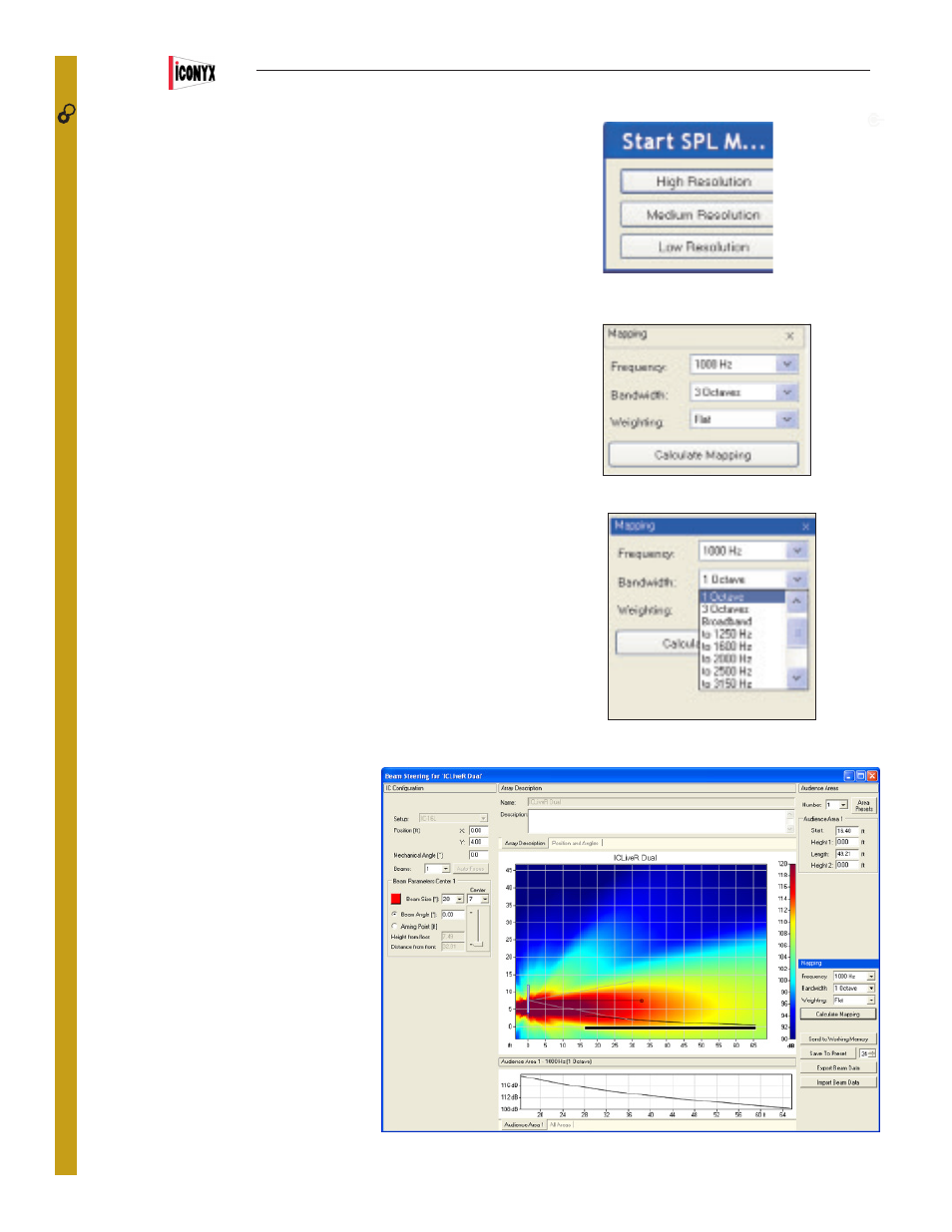
Note that at any point in the setup process you can click on the Calculate Map-
ping bar to tell the program to map the array’s performance on the audience area.
As soon as you press Calculate Mapping, a pop up screen will ask you to choose
the resolution of the simulation. Low Resolution simulations are much faster to
run than High Resolution ones. All you need to do to start the simulation is to
make your resolution choice by pressing one of the bars.
You also have the opportunity to choose the simulations Bandwidth, its Center
Frequency and its Weighting. The Frequency section lets you select center fre-
quencies from 100 to 10,000 Hz. The default selections for the Bandwidth section
allows you to run the simulation over 1 octave or 3 octave bands or Broadband.
You can change this by going to the Options window (F9), selecting the Appear-
ance tab and checking Show 1/3rd Octave. This adds a 1/3 octave selection to
the drop down Bandwidth menu and the opportunity to set a specific bandwidth
for the mapping simulation. In the graphic shown, for example, selecting “to 3150
Hz” would run the simulation over the frequency range of 1000 too 3150 Hz.
We’ll choose the default settings for this exercise, but you may want to try out all
the different settings to become familiar with them and the performance of steer-
able arrays.
Beam Angle aims the vertical beam up or
down. Try it out by selecting Beam Angle [*],
changing the number and observing its effect.
Note that after entering a new number you will
need to press Enter to initiate the change. You
will also need to do a new Calculate Mapping
to view the change. The old map will have
been wiped out by the program as you made
the change.
You can also check Focal Point [ft] and then
enter the exact location of the beam’s focal
point in Height from Floor and Distance from
Front.
Another way to position the beam’s focal point
is to use the mouse cursor to grab the end
point of the aiming axis and move it to the
desired location.
Try it out. It’s easy to do. The SPL levels in the
graphs will change as the setup parameters change.
27
CONTROL
46
Users Manual
IC
2