Geo d serial #1611 to above, 3 geo sub connectors – Nexo GEO D User Manual
Page 11
GEO
D
G
ENERAL
S
ET
-
UP
I
NSTRUCTIONS
Page
11/97
GEO D SERIAL #0100 to #1610
Please contact NEXO or your local distributor so that instructions and components are sent to you for
filter modification
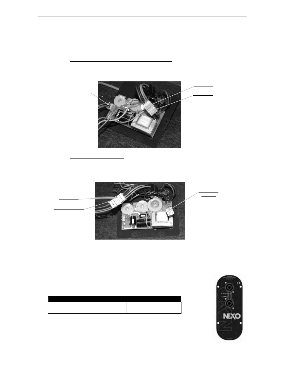
GEO D Serial #1611 to above
Configuring for Passive Mode (default configuration)
• Connector A & B are link together.
• Speaker Connector is in the CN1 (passive) connector located on the PCB
Configuring for Active Mode
• Speaker connector is directly plugged in connector B.
• Connector A is not used, PCB is bypassed.
2.1.3 GEO SUB connectors
The GEO SUB’s are connected to power amplifiers via NL4FC SPEAKON connectors (not supplied). A
wiring diagram is printed on the connection panel located on the back of each cabinet. The in/out pins of
the SPEAKON sockets are identified. The sockets are connected in parallel within the enclosures (see
the Connections Diagrams section of this manual).
NL4FC #
1- / 1+-
2- / 2+
GEO SUB
Rear 12”’s VLF - 8 Ω
1(-) Negative – 1(+) Positive
Front 18” VLF-LF - 8 Ω
2(-) Negative – 2(+) Positive
Connector B
Connector A
Speaker Connector
Connector B
Connector A
(unused)
Speaker Connector