Stuart Turner TFL Automatic Flow Switch User Manual
Page 8
- 8 -
Cont ...
Where secondary circuits are in use, the pump should be sited as close as possible to
the draw off points from the circuit.
Pipework Connections (General)
WARNINGS
Ensure pipework to and from pump is independently supported to
prevent forces being transferred to inlet and outlet branches of pump.
Do not introduce solder flux to pumps or pump parts manufactured
from plastic. All solder joints should be completed and flux residues
removed prior to pump connection.
Do not allow contact with oil or cellulose based paints, paint thinners
or strippers, acid based descalents or aggressive cleaning agents.
Do not allow scale or debris to enter pump. Fit inline strainers to
eliminate the problem in systems at risk.
Do not install a non-return valve, or devices
which contain non-return valves, in the
suction (inlet) pipework to the pump. The
pump must be free to vent to the supply
tanks at all times.
Noise transmission in pipework can be reduced by fitting flexible hoses to pump inlet and
outlet ports.
An installation pack which includes flexible hoses is available, consult Stuart Turner for
details.
We do not recommend location of the pumps in the roof space, since air locks can easily
result. If there is no alternative, please contact our technical sales department for advice.
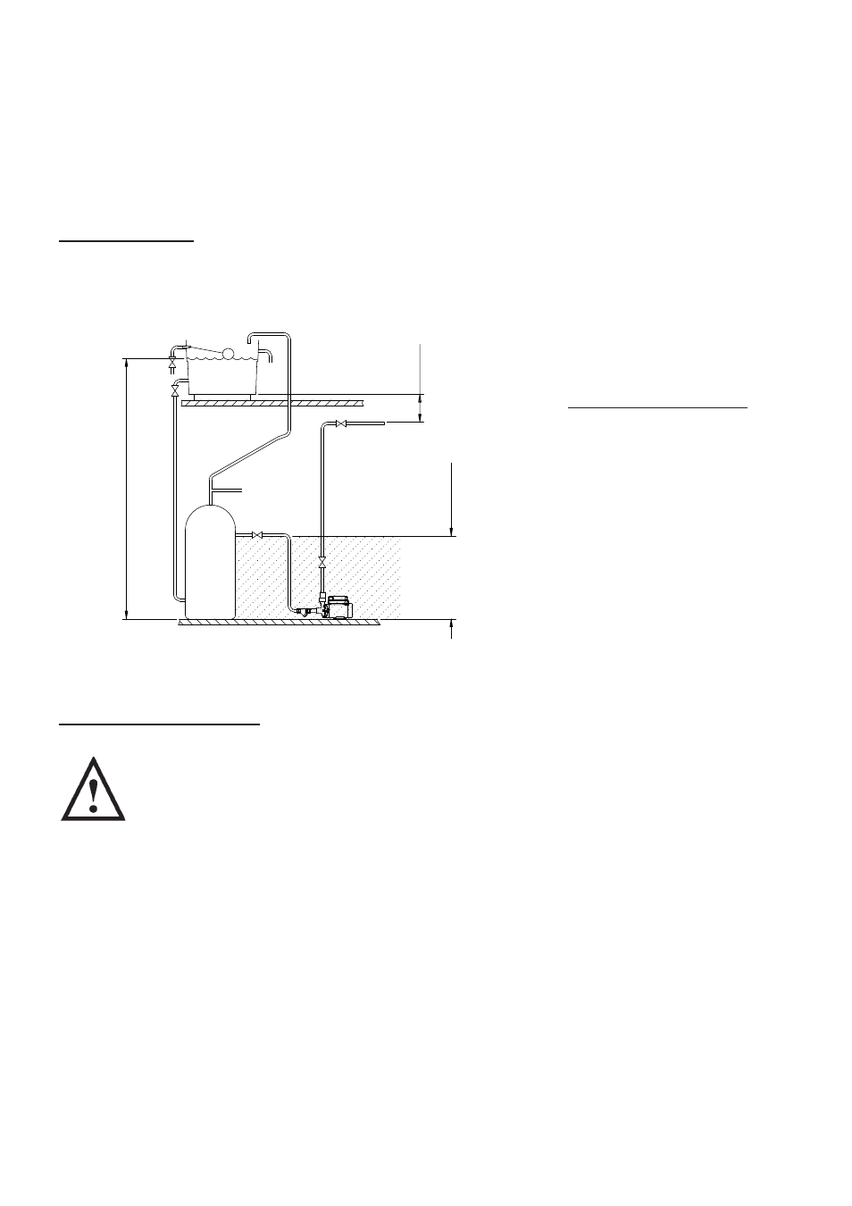
Pump Location (Hot Water Installation)
The preferred pump location is at floor level next to the hot water cylinder or a level that
is below the secondary tapping that feeds the pump. This will ensure the pump has access
to an air free water supply which is important for trouble free operation (Fig. 7).
Fig. 7
Preferred Pump Location
with pump at a level below
draw off tapping in cylinder.
Max. inlet head (consult limits of application section)
Min. inlet head
1
m
100
mm
min
preferred
area
hot water
services