Siting of the pump / pipework, Pump location (general) – Stuart Turner TFL Automatic Flow Switch User Manual
Page 7
- 7 -
SITING OF THE PUMP / PIPEWORK
WARNINGS:
The motor casing can become very hot under normal operating
conditions, care should be taken to ensure it cannot be touched
during
operation.
Pump Location
If possible site the pump in a location where in the unlikely event of a
liquid leak, any spillage is contained or routed to avoid electrics or
areas sensitive to liquid damage.
Care should be taken to protect pump from frost and freezing.
Always install isolating valves to both suction and delivery pipework.
Pump Location (General)
Locate the pump in dry, frost free position where it cannot be sprayed with water. It
should be positioned horizontally on its anti-vibration mounting feet and should not be
screwed down. It should be positioned as close to the liquid source as possible having a
minimum flooded suction head of 1 metre at all times.
Ensure the liquid flow is in the direction of the arrow that is marked on the flow switch
reed clamp (vertically upwards).
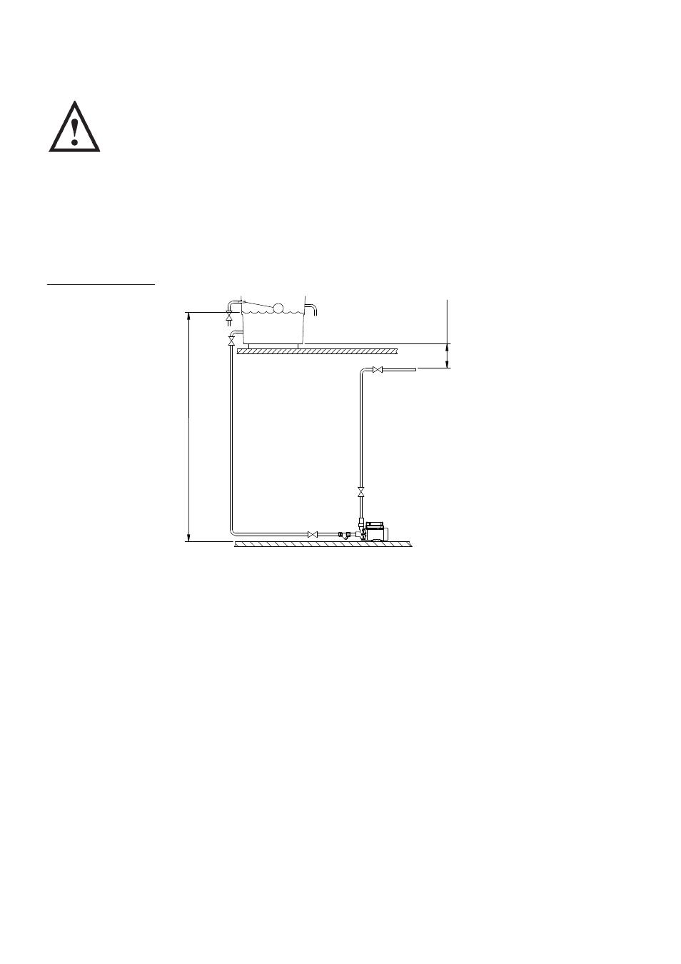
For the pump to function correctly, it must be installed in a positive head position, a
minimum gravity flow of approx. 0.6 l/min (RGFL/RGDFL/ESFL models) or approx. 1 l/min
(KFL, LFL and TFL models) is required from the highest outlet to operate the built-in flow
switch. This is normally achieved with a static head of 100 mm from base of storage tank
to the highest outlet in the system (Fig. 6).
Before deciding where to position the unit, check to ensure the static inlet head of liquid
above the pump (Fig. 6), does not exceed the maximum given in the limits of application
section.
The pump enclosure must be ventilated and there should be a minimum clearance of
80 mm between pump and housing on all sides.
The resilient anti-vibration mounting feet which are supplied as standard, are a
precaution to reduce noise transmission, however care must be taken when mounting the
pump that any noise is not amplified through loose panels, pipework or other mounting
medium.
Fig. 6
Diagram showing typical cold
water boosting installation.
Max. inlet head (consult limits of application section)
Min. inlet head
1
m
100
mm
min