Iv. operation – Sterling MS User Manual
Page 16
— 16 —
DX COIL EQUIPPED UNITS (OPTIONAL)
See Coil Installation/Maintenance Manual for Refrigerant
Piping, Liquid and Suction Line Components, Refrigerant
Charging and Thermal Expansion Valve Adjustment.
Remove coil cabinet access door located next to blower
section. Cut holes in fi xed door to allow suction and liquid
line passage. Provide weatherproof seal around suction
and liquid lines at piping plate when installed.
The DX Coil has a 300 ft/min. (1.524 m/s) minimum and
a 600 ft/min. (3.048 m/s) maximum velocity through the
coil requirement. This is due to prevention of coil icing or
condensate blow-off. To calculate the velocity through the
coil, apply the following formula:
Velocity =
Cooling Air Flow in CFM (m
3
/s)
through the coil
Coil Surface Area in ft
2
(m
2
)
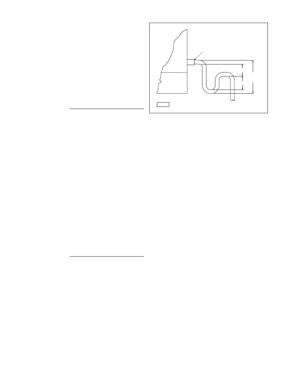
Condensate Drain piping must have a P-trap in line
immediately downstream of drain pan connection,
external to the unit, to prevent possible outside air
leakage into unit. The P-trap shall be of sufficient
differential to overcome negative pressure of the indoor
air blower. A minimum height difference of 2" (51mm) is
required (See Figure 16). Before unit operation begins,
the P-trap must be primed with either water (summer) or
glycol (winter).
CHILLED WATER COIL
EQUIPPED UNITS (OPTIONAL)
See Coil Installation/Maintenance Manual for General
Coil Piping Recommendations. Remove coil cabinet
access door, cut holes in door to allow chilled water piping
passage. Provide weatherproof seal around chilled water
pipes at piping plate when installed.
The Chilled Water Coil has a 600 ft/min (3.048 m/s)
maximum velocity through the coil requirement. This is
due to prevention of condensate blow-off. To calculate
the velocity through the coil apply the following formula:
Velocity =
Cooling Air Flow in CFM (m
3
/s)
through the coil
Coil Surface Area in ft
2
(m
2
)
Condensate Drain piping must have a P-trap in line
immediately downstream of drain pan connection,
external to the unit, to prevent possible outside air leakage
into unit. The P-trap shall be of suffi cient differential to
overcome negative pressure of the indoor air blower. A
minimum height difference of 2" is required (See Figure
16). Before unit operation begins, prime P-trap with either
water (summer) or glycol (winter).
EVAPORATIVE COOLER
EQUIPPED UNITS (OPTIONAL)
Refer to Evaporative Cooler Installation and Service
Manual for water and electrical connections.
Figure 16 - Drain Pan Connection
IV. OPERATION
GENERAL INFORMATION
Refer to Separated Combusion Indoor Gas-Fired Duct
Furnace Installation and Service Manual for specifi c
information regarding the heating operation of this unit.
All units are equipped with an intermittent ignition pilot
system. The pilot is lit and extinguished each cycle of unit
heating operation.
On natural gas units, the ignitor will continue to spark and
pilot gas will continue to fl ow until the pilot fl ame is proven.
LP (propane) units are equipped with 100% lockout. The
lockout function shuts off the main and pilot gas valves if
the pilot gas fails to ignite within 90 seconds of the onset
of trial for ignition.
The gas control system operates at 24 VAC and is
supplied by a stepdown transformer found in the electrical
cabinet that will match the unit line voltage specifi ed. See
Figures 13 through 15 for unit controls location.
Do not use a thermostatic fan control switch when either
two-stage fi ring or modulated gas controls are used.
GAS CONTROL SYSTEM
The standard unit comes equipped for single stage
operation. Unit heating operation is accomplished at
full input.
Each duct furnace is equipped with an individual ignition
control system which consists of the following components:
ignition control module, gas valve and pilot burner.
The ignition control module is the heart of the ignition
control system. This control initiates all gas fl ow, provides
means to light the pilot burner, proves and monitors the
pilot burner operation.
Drain Pan Connection
H
Total
Height
of Trap
X = 1/2 “H”
H = At Least 1 Inch Plus
Casing Static Pressure
D3887
Total Height Of Trap = X+ H + (1-1/2 X Pipe Diameter)
(without Insulation)
Unit
Housekeeping
Pad
X