Figure 15 - disconnect box locations – Sterling MS User Manual
Page 15
— 15 —
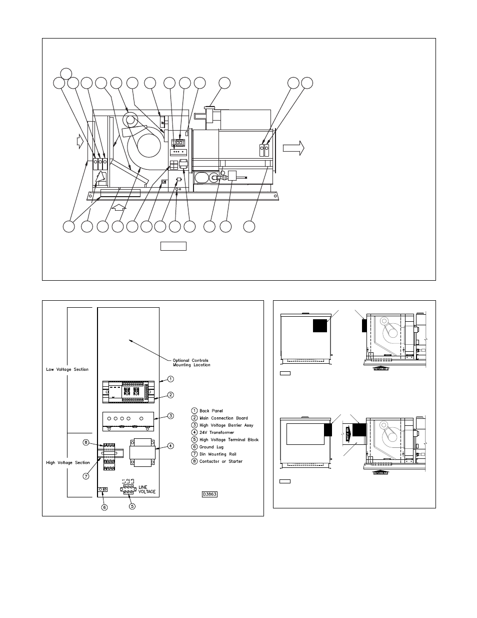
1. Mixed Air Controller
2. Return Firestat
3. Economizer
4. Filters
5. Blower Motor
6. Reverse Air Flow Switch
7. Clogged Filter Switch
8. High Voltage Barrier, Lamp
and Circuit Breaker Mount
9. Main Connection Board
with Fan Time Delay
and Function Relays
10. Power Venter Motor Assembly
(includes Relay and
Air Pressure Switch)
11. Ignition Module (not shown-
located in burner compartment)
12. Time Delay Freezestat
13. Supply Firestat
14. Duct Thermostat
15. Safety Limit Switch
16. Gas Valve
17. Primary High Limit Switch
18. Transformer
19. Electrical Wiring Inlet
20. High Voltage Terminal Block
21. Door Safety Switch
22. Contactor
23. Centrifugal Blower
24. Damper Motor
25. Outside and Return Dampers
26. Ambient Lockout
27. CO
2
Monitor
Figure 13B - Make-Up Air Unit-Standard Blower Cabinet, Single Duct Furnace with Various Options Shown
Figure 14 - Electrical Cabinet
Return Air Inlet
Outside Air Inlet
D4108
Disconnect Box
Disconnect Box Located On Outside Air Application
D4109
Disconnect Box
Disconnect Box Located On Outside Air Application
Field Ductwork
For Outside
Air Inlet
Figure 15 - Disconnect Box Locations
RETURN AIR
AIR FLOW
OUT
SIDE AIR
20
25
24
22
23
21
18
19
17
16
15
1
2
3
4
5
6
7
Dampers/Filters/
Blower Cabinet
8
9
10
12
13
Furnace
Cabinet
Electrical
Duct
14
26
27
D6572