Sterling MS User Manual
Page 11
— 11 —
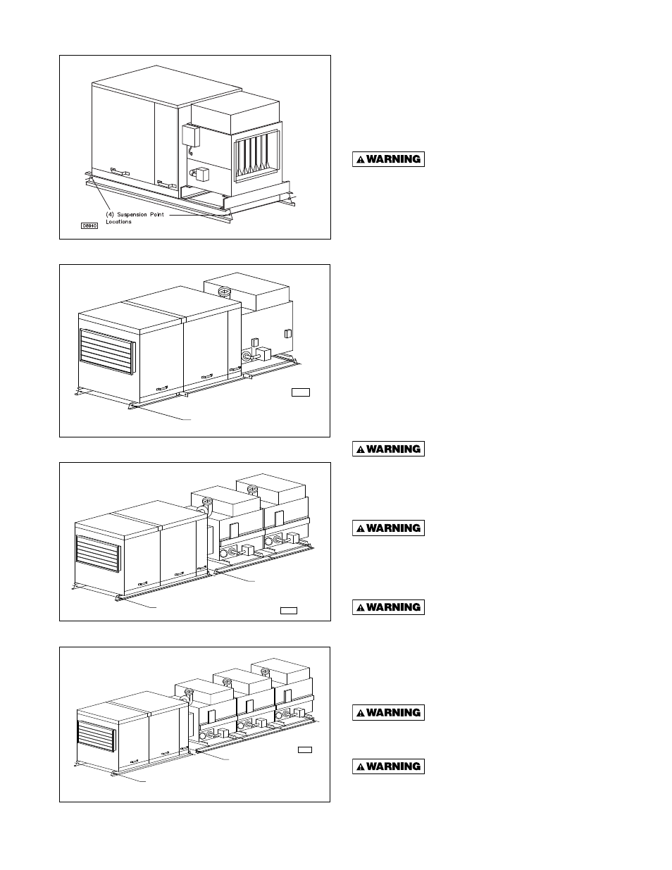
Figure 7 - Arrangement B & D
Capacities10/40
Figure 8 - Arrangement G
Capacities 10/40
Figure 9 - Arrangement G
Capacities 50/80
Figure 10 - Arrangement G
Capacity 12
D6554
(8) Suspension Point
Locations (4) On Each
Side Of Unit
D6555
(4) Suspension Point
Locations (2) At Each
End Of Air Handler Unit
(6) Suspension Point
Locations (3) On Each
Side Of Duct Furnace Unit
Both Units Must Be
Suspended At Same
Height For Proper
Fit Of Flex Connector
D6556
Both Units Must Be
Suspended At Same
Height For Proper
Fit Of Flex Connector
(4) Suspension Point
Locations (2) At Each
End Of Air Handler Unit
(8) Suspension Point
Locations (4) On Each
Side Of Duct Furnace Unit
INSTALLATION CLEARANCES
Minimum clearances to combustible material are shown
on the unit data plate. It is important that clearances
be maintained for servicing the unit, and that minimum
clearances are provided from the unit to combustible
material. Clearances around the fi eld installed optional
outside air hood (if unit is to be connected to one) must
be unobstructed. See Figure 11.
Under no circumstance should
combustible material be located within the specifi ed
clearances. Failure to provide proper clearance
could result in personal injury or property damage
from fi re.
Every gas appliance should be located with respect
to building construction and other equipment so as to
permit access to the unit. Clearances between vertical
walls and the vertical sides of the heater should be no
less than 18" (457mm). Minimum clearance between
the top of the heater and the ceiling is 6" (152mm). The
minimum clearance to the bottom of the furnace is 25"
(635mm). The minimum clearance from combustibles to
the fl ue collector is 6" (152mm). The minimum clearance
from combustibles to the vent pipe is 6" (152mm). See
Figure 11.
*It is recommended that adequate clearance be kept
to the bottom of the furnace(s) to make sure a service
technician can safely service the unit(s),
The unit should never be lifted by
furnace sections, blower housing/filter/sections,
motor mounts or fl ue connections. These are not
designed to support total weight of the unit, and may
break, causing personal injury or property damage!
Make certain that the lifting
methods used to lift the Make-Up Air Unit are
capable of supporting the weight of the heater
during installation. Failure to heed this warning
may result in property damage or personal injury.
Make certain that the structure to
which heater is to be mounted is capable of safely
supporting its weight. Under no circumstances
must the gas lines or the electrical conduit be
used to support the heater. Failure to heed these
warnings may result in property damage, personal
injury or death.
Open all disconnect switches before
installing the unit. Failure to do so may result in
personal injury or death from electrical shock.
Inspect the suspension and/or
support system for the make-up air unit to ensure that
all fasteners are tight and the unit is secure before
working underneath the unit. Failure to do so could
result in property damage, personal injury, or death.