Sterling MS User Manual
Page 14
— 14 —
MODULATING GAS CONTROL (OPTIONAL)*
Electronic: On units equipped with electronic modulating
control, follow control manufacturer’s installation
instructions for sensing of outlet air temperature.
*Also refer to the Separated Combustion Indoor Duct
Furnace Installation Manual supplied with your unit.
ELECTRICAL CONNECTIONS
HAZARDOUS VOLTAGE!
DISCONNECT ALL ELECTRIC
POWER INCLUDING REMOTE
DISCONNECTS BEFORE
SERVICING. Failure to
disconnect power before
servicing can cause severe
personal injury or death.
All electrical connections must conform to: the latest
edition of ANSI/NFPA No. 70, National Electrical Code,
and applicable local codes. In Canada, to the Canadian
Electrical Code, Part I CSA Standard C22.1.
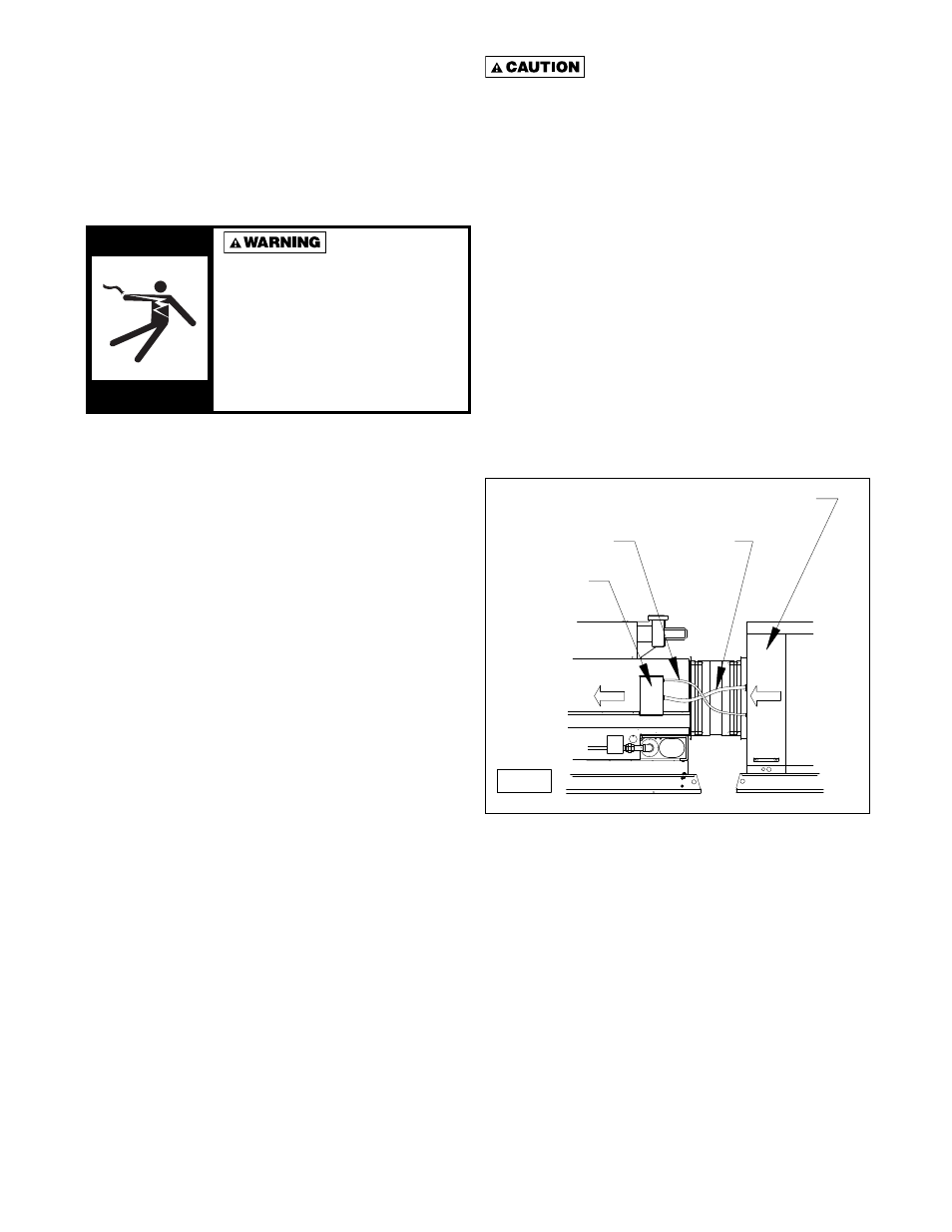
Single furnace make-up air packaged units are wired
at the factory and are ready to be connected. Multiple
furnace make-up air units are shipped in two parts, the air
handler section and the furnace section. After mounting
the two sections and installing the fl exible duct connector,
connect the free end of the fl exible conduits from the air
handler section to the junction box on the duct furnace.
Each wire has a distinctive marking. Connect each wire
to its respectively marked terminal in the duct furnace
junction box. See Figure 13A. Actual unit wiring will differ
according to the options chosen. Each unit is shipped
with its own wiring diagram; refer to this wiring diagram
for all electrical connections to the unit.
All line voltage and thermostat connections are made
in the Electrical Cabinet (See Figure 13B). Line voltage
connections are made at the High Voltage Terminal
Block. Thermostat connections are made at the Main
Connection Board (See Figure 14).
Do not use any tools (i.e. screwdriver,
pliers, etc.) across terminals to check for power. Use
of a voltmeter is recommended.
Locate the thermostat in accordance with the instructions
supplied with the thermostat. All fi eld wiring must have
a minimum temperature rating of 185°F (85°C). Control
wiring shall be a minimum of 18 gauge wire size. Control
wiring must be sized for length of run.
Locate line voltage disconnect box per local codes. If
mounting the disconnect box to the unit, never mount
it to a unit access panel. Possible locations include
the front of the blower or fi lter section (See Figure 15).
Electrical conduit must be routed so as not to interfere
with removal of any access panel.
NOTICE: Should any original wire supplied with the unit
have to be replaced, it must be replaced with wiring
having a temperature rating of at least 221°F (105°C).
Figure 13A
AIR FLOW
AIR FLOW
Electrical Cabinet
Air Handler
Junction Box
Duct Furnace
Conduit
Low Voltage
Conduit
Line Voltage
D03304
*
*
*
*
*
*
*
*
**
***