Figure 2 – Sterling QVSB User Manual
Page 4
4
Table 1 – Performance and Specifi cation Data – Separated Combustion Blower Unit Heater
Unit
Size
100 125 150 175 200 225 250 300 350 400
PERFORMANCE DATA ‡
Input
BTU/Hr
100,000 125,000 150,000 175,000 200,000 225,000 250,000 300,000 350,000 400,000
(kW)
(29.3)
(36.6)
(43.9)
(51.2)
(58.6)
(65.9)
(73.2)
(87.8)
(102.5)
(117.1)
Output
BTU/Hr
80,000 100,000 120,000 140,000 160,000 180,000 200,000 240,000 280,000 320,000
(kW)
(23.4)
(29.3)
(35.1)
(41.0)
(46.9)
(52.7)
(58.6)
(70.3)
(82.0)
(93.7)
Thermal Effi
ciency
(%)
80 80 80 80 80 80 80 80 80 80
Free
Air
Delivery
CFM
1,200 1,575 1,975 2,300 2,400 2,600 2,850 3,950 4,600 4,800
(cu. m/s)
(0.566)
(0.743)
(0.932)
(1.086)
(1.133)
(1.227)
(1.345)
(1.864)
(2.171)
(2.266)
Air
Temperature
Rise
Deg.
F. 62 59 56 56 62 64 65 56 56 62
(Deg. C)
(34)
(33)
(31)
(31)
(34)
(36)
(36)
(31)
(31)
(34)
Outlet
Velocity
FPM
880 950 1030 1045 965 935 930 1080
1090 1000
(m/s)
(4.47)
(4.83)
(5.23)
(5.31)
(4.90)
(4.75)
(4.72)
(5.49)
(5.54)
(5.08)
Full Load Amps at 115V
8.3
9.8
10.6
10.6
15.2
15.2
15.2
15.2
18.6
18.6
MOTOR DATA: Motor
HP 1/4 1/3 1/2 1/2 3/4 3/4 3/4 3/4 1 1
Motor
(kW) (0.19) (0.25) (0.37) (0.37) (0.56) (0.56) (0.56) (0.56) (0.75) (0.75)
Motor
Type SPH SPH SPH SPH SPH SPH SPH SPH
cap.start
cap.start
R.P.M.
1725 1725 1725 1725 1725 1725 1725 1725 1725 1725
Amps
@
115V 5.1 6.6 7.4 7.4 12.0 12.0 12.0 12.0
15.4 15.4
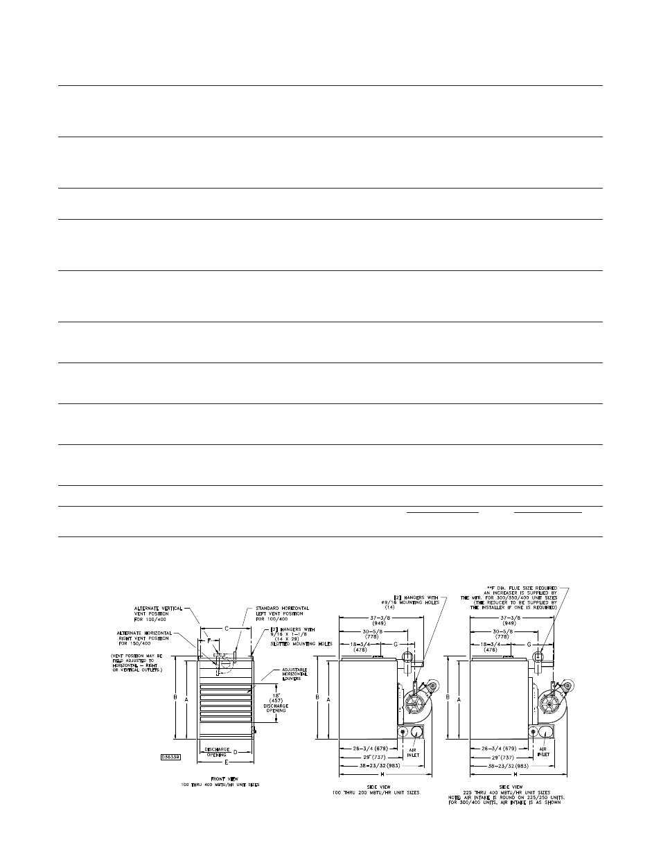
DIMENSIONAL DATA in. (mm)
“A” Height to Top of Unit
31-1/4
31-1/4
36-1/4
36-1/4
36-1/4
36-1/4
36-1/4
36-1/4
36-1/4
36-1/4
(794)
(794)
(921)
(921)
(921)
(921)
(921)
(921)
(921)
(921)
“B” Height to Top of Hanger
34-1/16
34-1/16
39-1/16
39-1/16
39-1/16
39-1/16
39-1/16
39-1/16
39-1/16
39-1/16
(865)
(865)
(992)
(992)
(992)
(992)
(992)
(992)
(992)
(992)
“C” Hanging Distance Width
14-3/4
17-1/2
17-1/2
20-1/4
23
25-3/4
28-1/2
34
39-1/2
45
(375)
(444)
(444)
(514)
(584)
(654)
(724)
(864)
(1003)
(1143)
“D”
Discharge
Opening
Width
15-3/8 18-1/8 18-1/8 20-7/8 23-5/8 26-3/8 29-1/8 34-5/8 40-1/8 45-5/8
(391) (460) (460) (530) (600) (670) (740) (879) (1019) (1159)
“E”
Width
of
Unit
17-7/8 20-5/8 20-5/8 23-3/8 26-1/8 28-7/8 31-5/8 37-1/8 42-5/8 48-1/8
(454)
(524)
(524)
(594)
(664)
(733)
(803)
(943)
(1083)
(1222)
“F” to Centerline of Flue
5-7/8
7-1/4
7-1/4
8-5/8
10
11-1/4
12-3/4
15-1/2
18-1/4
21
(149)
(184)
(184)
(219)
(254)
(286)
(324)
(394)
(464)
(533)
“G” Hanging Distance Depth
18-1/2
18-1/2
18-1/2
20
20
23
23
23
23
23
(470)
(470)
(470)
(508)
(508)
(584)
(584)
(584)
(584)
(584)
“H” Depth to Rear of Housing
42-3/4
44-3/8
44-3/8
47-3/16
47-3/16
50-7/8
48
50-7/8
50-7/8
51
(1086)
(1127)
(1127)
(1199)
(1199)
(1292)
(1219)
(1292)
(1292)
(1295)
Flue
Size
Dia-in.**
4 4 4 4 5 5 5 6 6 6
(Dia-mm)
(102)
(102)
(102)
(102)
(127)
(127)
(127)
(152)
(152)
(152)
Air
Inlet
Size-in.
4 4 4 4 5 5 5 6 6 6
(mm)
(102)
(102)
(102)
(102)
(127)
(127)
(127)
(152)
(152)
(152)
Blower
Size-in.
9 10 10 12 12 12 12 (2)10
(2)12
(2)12
Gas
Inlet-Natural
Gas-in.
1/2 1/2 1/2 1/2 1/2 3/4 3/4 3/4 3/4 3/4
Gas
Inlet-LP
Gas-in.
1/2 1/2 1/2 1/2 1/2 ←
1/2 or 3/4
→
Approx.
Shipping
Wt.
lb.
298 330 362 394 426 458 490 558 618 678
(kg)
(135)
(150)
(164)
(179)
(193)
(208)
(222)
(253)
(280)
(308)
DIMENSIONS .XXX STANDARD UNITS
DIMENSIONS IN PARENTHESIS (XXX) MILLIMETERS
Figure 2
‡ Ratings shown are for unit installations at elevations between 0 and 2000 ft. (610m). For unit installations in USA above 2000 ft. (610m), the unit input must be derated 4% for each
1000 ft. (305m) above sea level; refer to local codes, or in absence of local codes, refer to the latest edition of the National Gas Code, ANSI Standard Z223.1 (N.F.P.A. No. 54).
For installations in Canada, any references to deration at altitudes in excess of 2000 ft. (610m) are to be ignored. At altitudes of 2000 to 4500 ft. (610m to 1372m), the unit must be
derated to 90% of the normal altitude rating, and be so marked in accordance with the ETL certifi cation.
LEGEND: SPH = SPLIT PHASE
CAP. START = CAPACITOR START