Installation – Sterling QVSB User Manual
Page 15
15
INSTALLATION
(continued)
BLOWER SET UP
The drive ratio of the motor and blower sheaves has
been preset at the factory for a temperature rise of
65°F at 0 inch W.C. with no external duct work on sys-
tem. If the unit is to be operated under different air fl ow
or pressure requirements, the drive ratio must be altered
by means of the adjustable sheave on the blower motor,
Figure 15.
1. Ensure that all packing material, support blocks,
etc. have been removed from the unit.
2. Adjust the blower drive belt tension by means of
the two tension bolts on the blower motor base.
When proper tension has been achieved, the mid-
point defl ection of the belt will be 3/4 inch when
subjected to a 5 lb force.
3. Recheck all electrical connections.
4. When power is applied, ensure that the motor and
blower are rotating in a clockwise direction when
viewed from the drive side.
5. Measure the current draw of the motor.
The “at speed” current draw of the
motor must never exceed that specifi ed on the motor
rating plate or severe damage to the motor will
result!
BLOWER DRIVE ADJUSTMENT
Never attempt to adjust the drive
belt without fi rst disconnecting all electrical
power to the unit or severe personal injury may
result!
1. Remove the belt guard and loosen the belt tension
bolts on the blower motor base.
2. Loosen the set screw on the adjustable half of the
motor sheave. To increase the blower speed, turn
the adjustable half of the sheave clockwise, counter
clockwise to slow the blower. Retighten the set
screw.
3. Realign the blower and motor sheaves if necessary.
4. Adjust the belt tension as specifi ed in the BLOWER
SET UP section under step 2.
5. Replace the belt guard.
Never operate the unit without
the belt guard in place or severe personal injury
may result!
6. Check that the air fl ow of the unit, the rpm and
current draw of the blower motor and the temperature
rise are within the limits specifi ed in Table 1, the
blower motor rating plate and the rating plate on the
unit, respectively.
Never operate the unit beyond the
specified limits or severe damage to, and or
premature failure of, the unit will result!
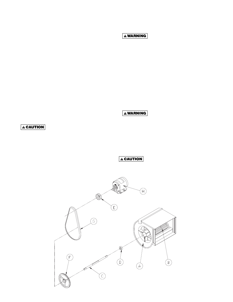
NOTE: THE BLOWER ASSEMBLY FOR
THE 100/250 UNITS CONSISTS OF 1 WHEEL,
1 HOUSING, 1 SHAFT AND 1 BEARING SET.
FOR 300/400 UNITS THE BLOWER ASSEMBLY
CONSISTS OF 2 WHEELS, 2 HOUSINGS, 1 SHAFT
AND 1 BEARING SET.
* PART DESCRIPTION
A. Blower Housing
B. Blower Wheel
C. Blower Shaft
D. Bearings
E. Drive Pulley (standard)
F. Driven Pulley (standard)
G. V-Belt
H. Motor
Figure 15 - Motor & Blower Assembly*