Primary air shutter adjustment, Table 5 - main burner orifi ce schedule – Sterling QVSB User Manual
Page 18
18
Table 5 - Main Burner Orifi ce Schedule*
PRIMARY AIR SHUTTER ADJUSTMENT
After the unit has been operating for at least 15
minutes, adjust the primary air fl ow to the burners. Turn
the friction-locked, manually-rotated air shutters
clockwise to close, or counterclockwise to open (see
Figures 16, 18 and 20).
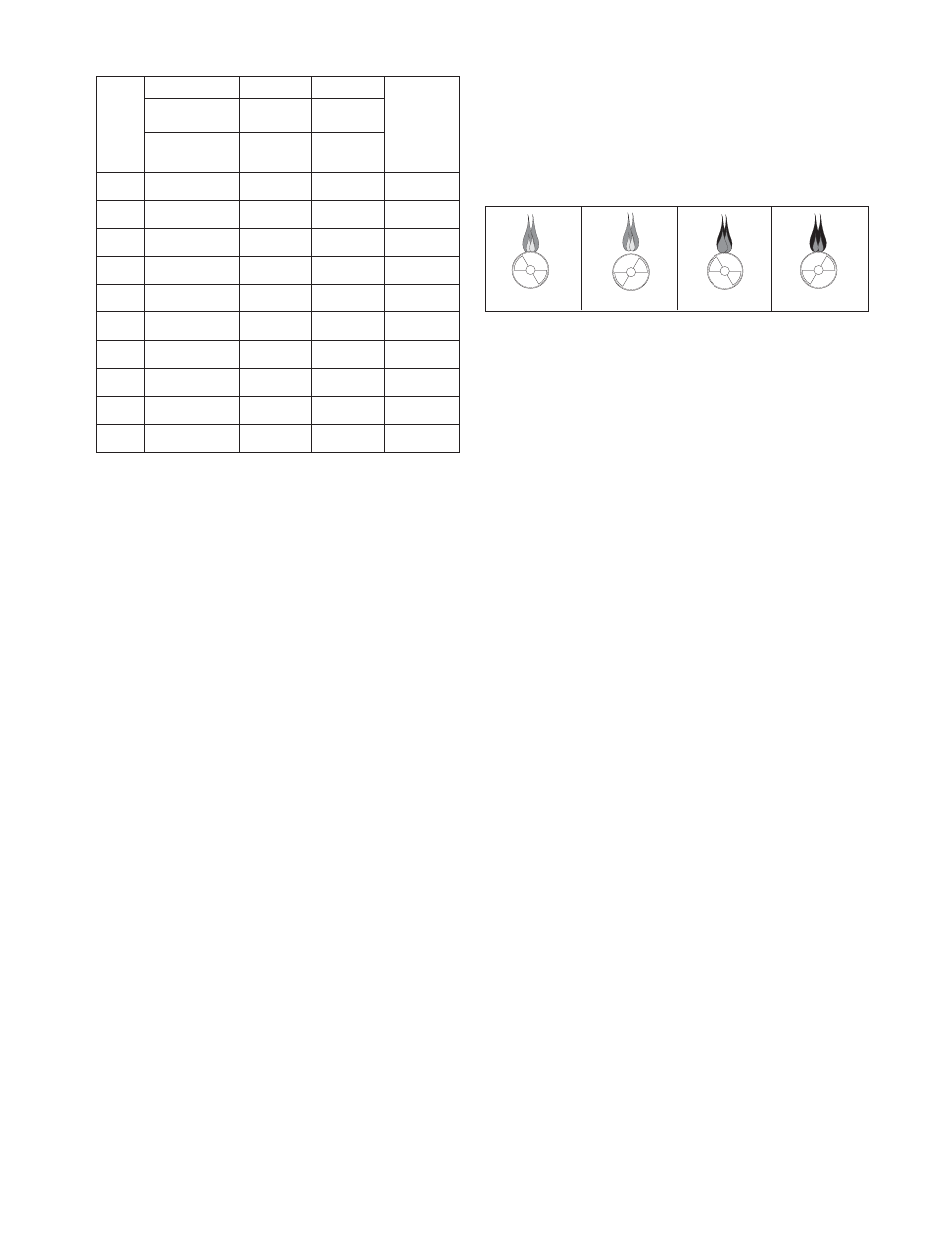
For correct air adjustment, close the air shutter until
yellow tips in the fl ame appear. Then open the air
shutter to the point just beyond the position where
yellow tipping disappears. Refer to Figure 17.
*
INPUT
IN
1000
BTU
2500 BTU/Ft
3
(93.1 MJ/m
3
)
PROPANE
TYPE OF GAS
NATURAL
1075 BTU/Ft
3
(40.1 MJ/m
3
)
NO. OF
BURNER
ORIFICES
4
5
6
7
8
9
10
12
14
16
100
125
150
175
200
225
250
300
350
400
FT
3
/HR
ORIFICE DRILL
FT
3
/HR
ORIFICE DRILL
FT
3
/HR
ORIFICE DRILL
FT
3
/HR
ORIFICE DRILL
FT
3
/HR
ORIFICE DRILL
FT
3
/HR
ORIFICE DRILL
FT
3
/HR
ORIFICE DRILL
FT
3
/HR
ORIFICE DRILL
FT
3
/HR
ORIFICE DRILL
FT
3
/HR
ORIFICE DRILL
96
42
120
42
140
42
163
42
186
42
210
42
233
42
280
42
326
42
372
42
40
54
50
54
60
54
70
54
80
54
90
54
100
54
120
54
140
54
160
54
* This schedule is for units operating at normal altitudes of 2000 ft. (610m) or
less. SPECIAL ORIFICES ARE REQUIRED FOR INSTALLATIONS ABOVE
2,000 FT. (610M).
When installed in Canada, any references to deration at altitudes in excess of
2000 feet (610m) are to be ignored. At altitudes of 2000 to 4500 feet (610 to
1372m), the unit heaters must be orifi ced to 90% of the normal altitude rating,
and be so marked in accordance with the ETL certifi cation.
NORMAL
(HARD FLAME)
LIFTING
(TOO MUCH AIR)
YELLOW TIPPING
(MARGINAL)
YELLOW FLAME
(TOO LITTLE AIR)
NOTICE: There may be momentary and spasmodic
orange fl ashes in the fl ame. This is caused by the
burning of airborne dust particles, and not to be
confused with the yellow tipping, which is a stable
or permanent situation when there is insuffi cient
primary air.
Figure 17 - Main Burner Flames
PILOT ADJUSTMENT
1. Remove the pilot adjustment cap.
2. Adjust the pilot screw to provide a properly sized
fl ame.
3. A proper pilot fl ame is a soft steady fl ame that
envelops 3/8 to 1/2-inch (9.5 to 12.7mm) of the
fl ame sensor.
4. Replace the pilot adjustment cap.
MANIFOLD PRESSURE ADJUSTMENT
If the manifold pressure requires minor adjustment,
remove the cap from the pressure regulator and turn
the adjustment screw clockwise to increase the
pressure, or counterclockwise to decrease the
pressure. The adjusted manifold pressure should not
vary more than 10% from the pressures specified in
Table 5.
MANIFOLD PRESSURE
If a decrease above 10% is desired, please contact
Technical Service for verifi cation of proper operations.
HEATING VALUE
3.5" W.C.
(0.9 kPA)
10.5" W.C.
(2.6 kPA)
MANIFOLD
PRESSURE