Sterling QVSB User Manual
Page 26
26
INSTALLATION INSTRUCTIONS
FOR FIELD REPLACEMENT OF POWER VENTER MOTOR
TOOLS AND PARTS NEEDED:
Wire Stripper and Crimper; Slotted Head and #2 Phillips
Head Screwdriver; 3/8" Wrench; 1/8" Allen Wrench (long
handle); marker; (1) 1/4" push on terminal for Wire.
NOTES:
1) Remove the cover from the Relay Junction Box
(Item 1) by removing two screws (Item 2) top and
bottom. Disconnect both wires from the motor lead
ends. One is connected to terminal #4 on the venter
relay, and the other is connected with a wire nut to a
black wire.
2) Remove the sensing tube (Item 3) from the Pressure
Switch/Mounting Bracket (Item 3) at motor end only.
Separated Combustion Units: Remove both tubes at
motor end only - note location.
3) Mark locations of the Relay Junction Box and
Pressure Switching Mounting Brackets along with
the Motor (Item 10) mounts on the Mounting
Adapter Plate (Item 4) - using a marker.
4) Remove nut (Item 5) that secures the Motor Support
Shipping Bracket (Item 6) to the Mounting Adapter
Plate. Pull this bracket away from the Motor
Mounting Adapter Plate.
5) Remove three phillips head screws (Item 7) on the
Motor mounting Adapter Plate. Remove the Motor/
Blower Wheel/Adapter Plate assembly from the
Power Venter Blower Housing (Item 8).
6) Remove the Blower Wheel (Item 9) from the motor
shaft - by removing the set screw (Item 14) using a
1/8" Allen Wrench.
7) Remove the three Motor Mounting Nuts (Item 5),
Space Washers (Item 11), and Screws (Item 12). Do
not lose these parts! Using caution - the motor will
disengage from the Mounting Adapter Plate, along
with the Relay Junction Box and Pressure Switch
Mounting Brackets will also disengage.
8) Reverse order to install the new Power Venter Motor.
9) TEST FIRE THE UNIT FOR A FEW CYCLES,
MAKING SURE THAT THE UNIT IS OPERATING
SATISFACTORY.
Never service any compartment
without fi rst disconnecting all electrical and gas
supplies. Refer to unit’s wiring diagram. This
replacement must be performed only by a
qualifi ed technician.
NOTICE: All hardware (screws, nuts, washers) that
will be removed from the unit will be reused for this
motor replacement. DO NOT LOSE ANY OF THESE
PARTS.
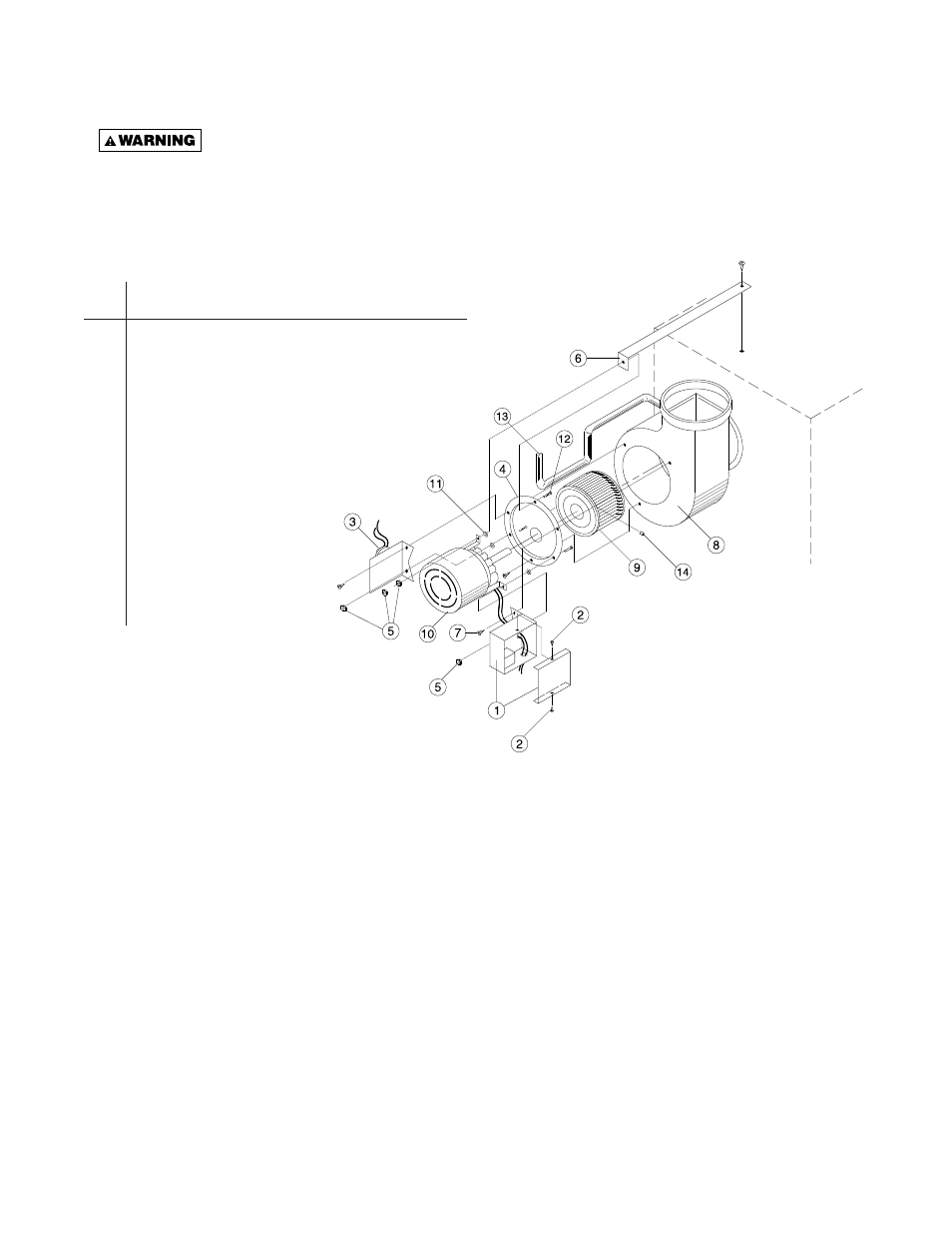
Figure 22 - Identifi cation of Parts
REF.
NO. DESCRIPTION
1
Relay Junction Box/Mounting Bracket Assembly
2
#8 Drill Screws (2 required)
3
Pressure/Mounting Bracket Assembly
4
Mounting Plate Adapter
5
Keps Nut w/External Tooth Lockwasher
(4
required)
6
Motor Support Shipping Bracket
7
Phillips Head Screws (3 required)
8
Power Venter Blower Housing
9
Blower Wheel
10 Motor
11 Space
Washers
(3
required)
12 Machine
Screw
(3
required)
13 Sensing
Tube
14 Set
Screw