Wrng procedure – Yokogawa µR10000 User Manual
Page 65
IM 04P01B01-01E
2-10
Wrng Procedure
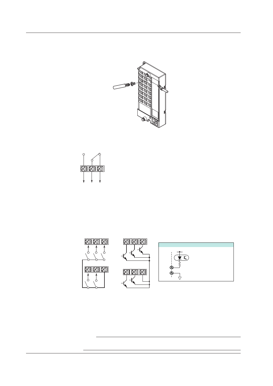
1.
Turn OFF the recorder and remove the terminal cover.
2.
Connect the input/output signal wires to the terminals.
Philips
screwdriver
Crimp-on lug with
insulation sleeves
3.
Replace the terminal cover and fasten it with screws.
The proper torque for tightening the screws is 0.6 N•m.
Alarm Output Relay Termnals and FAIL/Chart End Output Relay Termnals
C
NO
NC
NO (Normally Opened), C (Common), NC (Normally Closed)
• Relay Contact Output Specfcatons
Output type:
Relay
Contact rating:
250 VAC (50/60 Hz)/3 A, 250 VDC/0.1 A (resistive load)
Dielectric strength:
1500 VAC at 50/60 Hz for one minute (between output
terminals and the ground terminal)
Remote Control Input Termnals
1
2
3
4
5
C
1
2
3
4
5
C
C
1 to 5
Internal circuit
Input type:
Photocoupler isolation
Shared common (C)
Allowable input voltage:
5 VDC
5V
1 to 5 (Remote control input terminals), C (Common)
Transistor input
(open collector)
Relay contact input
(voltage-free contact)
• Relay Contact Input/Transstor Input Specfcatons
Input signal:
• Voltage-free contact: Contact closed at 200 Ω or less and
contact open at 100 kΩ or greater
• Open collector: 0.5 V or less (30 mADC) when turned ON,
leakage current of 0.25 mA or less when turned OFF
Dielectric strength:
500 VDC for one minute between input terminals and the
ground terminal
Note
To reduce noise, use a shielded cable for the wiring of the remote control input terminals.
Connect the shield to the ground terminal of the recorder.
2.4 Optonal Termnal Wrng