App index – Yokogawa µR10000 User Manual
Page 33
1-17
IM 04P01B01-01E
Funct
onal
Explanat
on
and
Setup
Gu
de
For the procedure to set the functions, see section 1.10, “Function Setup Guide.”
1
2
3
4
5
6
7
8
9
10
11
12
App
Index
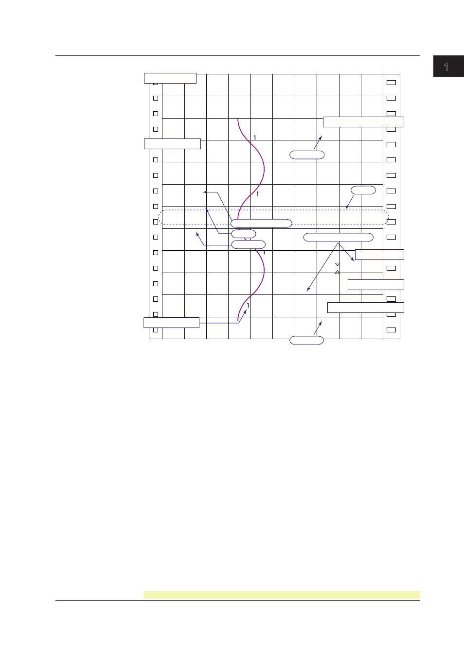
Prntout Example on the Dot Model
Alarm printout
Message printout
Manual printout
Channel printout
Periodic printout
Scale
Buffer overflow mark
Time tick
Time tick
New chart speed printout
Delta computation
Alarm
Time tick
Recording start printout
Nov.09.04 16:00
1 223.5mg/cm
3
2 437.2µS/cm
3 H 591.6°C
4 -0.222V
5 -0.665V
6 L -0.448V
_50mm/h*14:55
_08:00*25mm/h
09:52*START#205 ABCDEF
1H3*10:09
1H3 10:05
Nov.09.04
13:50
1 218.7mg/cm
3
2 390.6µS/cm
3 H 598.4°C
4 d -0.222V
5 -0.995V
6 L -0.448V
0.0
500.0
1CH
mg/cm
3
50mm/h_
Channel Prntout (Dot Model Only)
Prints the channel number or tag by the trend recording. The channel number or tag
is printed every approximately 25 mm on the chart paper. The channel printout can be
enabled or disabled. By default, the channel printout is enabled.
Switching between channel number printout and tag printout: Section 7.7
Setting the periodic printout (interval, reference time, types of measured values, and
periodic printout ON/OFF): Section 7.8
Turning printout ON/OFF (channel printout, alarm printout, recording start printout, new
chart speed printout, and scale printout for periodic printout): Section 7.7
Setting the time format (alarm printout, message printout, recording start printout, and
new chart speed printout): Section 7.16
Turning recording and printout ON/OFF for each channel (trend recording and periodic
printout): Section 6.6
Executing manual print: Section 3.7
Setting the message string and printing messages: Sections 6.8 and 3.10
Clearing the alarm printout buffer: Section 3.9
Printing settings: Section 3.8
1.4 Recordng