3-2. wiring other galvanic sensors, 3-3. wiring polarographic sensors, 3-4. wiring sensors with vp connector – Yokogawa DO202 2-Wire Dissolved Oxygen Analyzer User Manual
Page 35
IM 12J05C01-01E
Installation and Wiring 3-4
3-3-2. Wiring other galvanic sensors
Consult the users manual for the color identification
of the sensor cable.
- The temperature sensor has two wires and must
be connected to the terminal 11 and 12.
- The measuring electrode: the cathode must be
connected to terminal 13.
- The reference electrode: the anode must be
connected to terminal 15.
- The overall shield of the cable must be connected
to terminal 14 if there is one available.
- Place the jumper in the GALVANIC position.
3-3-3. Wiring polarographic sensors
Consult the owners manual for the color identifica-
tion of the sensor cable.
- The temperature sensor has two wires and must
be connected to the terminal 11 and 12.
- The measuring electrode: the cathode must be
connected to terminal 17.
- The reference electrode: the anode must be
connected to terminal 18.
- The overall shield of the cable must be connected
to terminal 14 if there is one available.
- Place the jumper in the POLAROGRAPHIC position.
3-3-4. Wiring sensors with Vp connector
Consult the owners manual for the color identifica-
tion of the sensor cable
- The temperature sensor has two wires and must
be connected to terminal 11 and 12
- Polarographic : the measuring electrode
(cathode) must be connected to terminal 17
- Polarographic : the reference electrode (anode)
must be connected to terminal 18
- Galvanic : the measuring electrode (cathode)
must be connected to terminal 13
- Galvanic : the reference electrode (anode) must
be connected to terminal 15
- The overall shield of the cable must be connected
to 14
- Place the jumper in the Polarographic or Galvanic
position
Figure 3-6. Connections DO
Figure 3-7. Terminal indentification labels
A-17 pol. 13 galv.
B-18 pol. 15 galv.
C
D
E-11
F-12
S-14
temp
11
12
12
13
14
14
16
15
13
14
14
16
15
17
11
17
11 Red
12 Blue
15 Core 16 Screen
White Co-axial cable
13 Core 17 Screen
Brown Co-axial Cable
WF10 Cable
14 Overall Screen
TRANSMITTER / CONVERTER
11
12
17
13
15
16
14
A
C
Overall
shield
B
D
Screen
E
Red
White
Blue
Brown
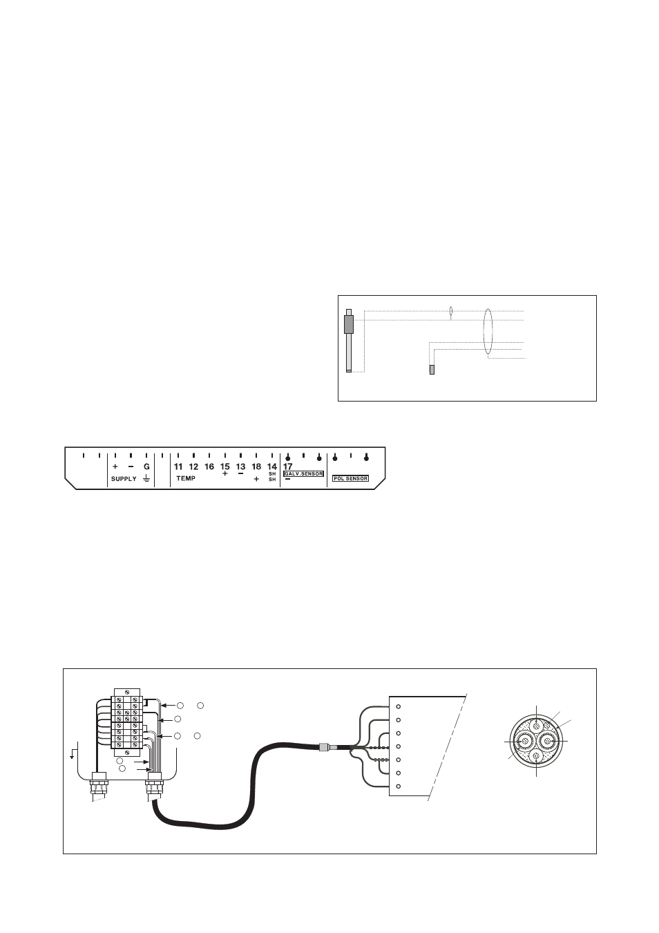
Figure 3-8. Connection of WF10 extension cable and BA10/BP10 junction box
3-3-5. Sensor cable connections using junction
box (BA10) and extension cable (WF10)
Where a convenient installation is not possible using
the standard cables between sensors and trans-
mitter, a junction box and extension cable may be
used. The Yokogawa BA10 junction box and the
WF10 extension cable should be used. These items
are manufactured to a very high standard and are
necessary to ensure that the specifications of the
system are not compromised. The total cable length
should not exceed 30 metres (including DO sensor
cable).