General specifications, 1. specifications – Yokogawa DO202 2-Wire Dissolved Oxygen Analyzer User Manual
Page 12
IM 12J05C01-01E
General Specifications 2-1
2-1. Specifications
A. Input specifications
The DO202 accepts output from membrane covered
Dissolved Oxygen sensors. These sensors can be
Galvanic type, where the sensor generates its own
driving voltage or Polarographic type, where the sen-
sor uses external driving voltage from the transmitter.
The input range is 0-50 μA for Galvanic sensors and 0-
1 μA for Polarographic sensors. For temperature com-
pensation the DO202 accepts Pt1000Ω (DO30 sensor)
and 22kΩNTC elements (OXYFERM and OXYGOLD
sensors)
B. Measuring range
- Dissolved Oxygen
:
0 - 50 ppm (mg Oxygen
per kg water);
0 - 1999 ppb (mg Oxygen
per 1000 kg water) and 0
- 600 % Saturation of Air
in Water.
- Temperature
: -20 to 150ºC (-4 to 302ºF).
C. Temperature compensation
Automatic using Pt1000Ω or 22kΩNTC or
manual Range 0 - 100ºC (32 to 212 ºF)
D. Calibration
Semi-automatic one or two point calibration in air
or in water using solubility tables of ISO 5814.
The influence of pressure and salinity is taken
into account when these specifications are
entered. Also a two point manual calibration is
possible.
E. Transmission Signals
Isolated output of 4-20 mA DC, Burn up (21 mA)
or Burn dwon (3.6 mA when HART® comm. non-
used, 3.9 mA when HART comm. used) or pulse
of 21 mA to signal failure.
F. Logbook
Software record of important events and
diagnostic data. Available through digital
communication.
G. Display
Custom liquid crystal display, with a main display
of 3 1/2 digits 12.5 mm high. Message display of
6 alphanumeric characters, 7 mm high.
H. Power supply
Nominal 24 volt DC loop powered system
DO202G-A : up to 40 volts
DO202S-A, -N: up to 31.5 volts
DO202G/S-F, -P: 9-24, 9-17.5 (FISCO) VDC /
26.0 mA
DO202S-B, -D: 9-32 VDC / 26.0 mA
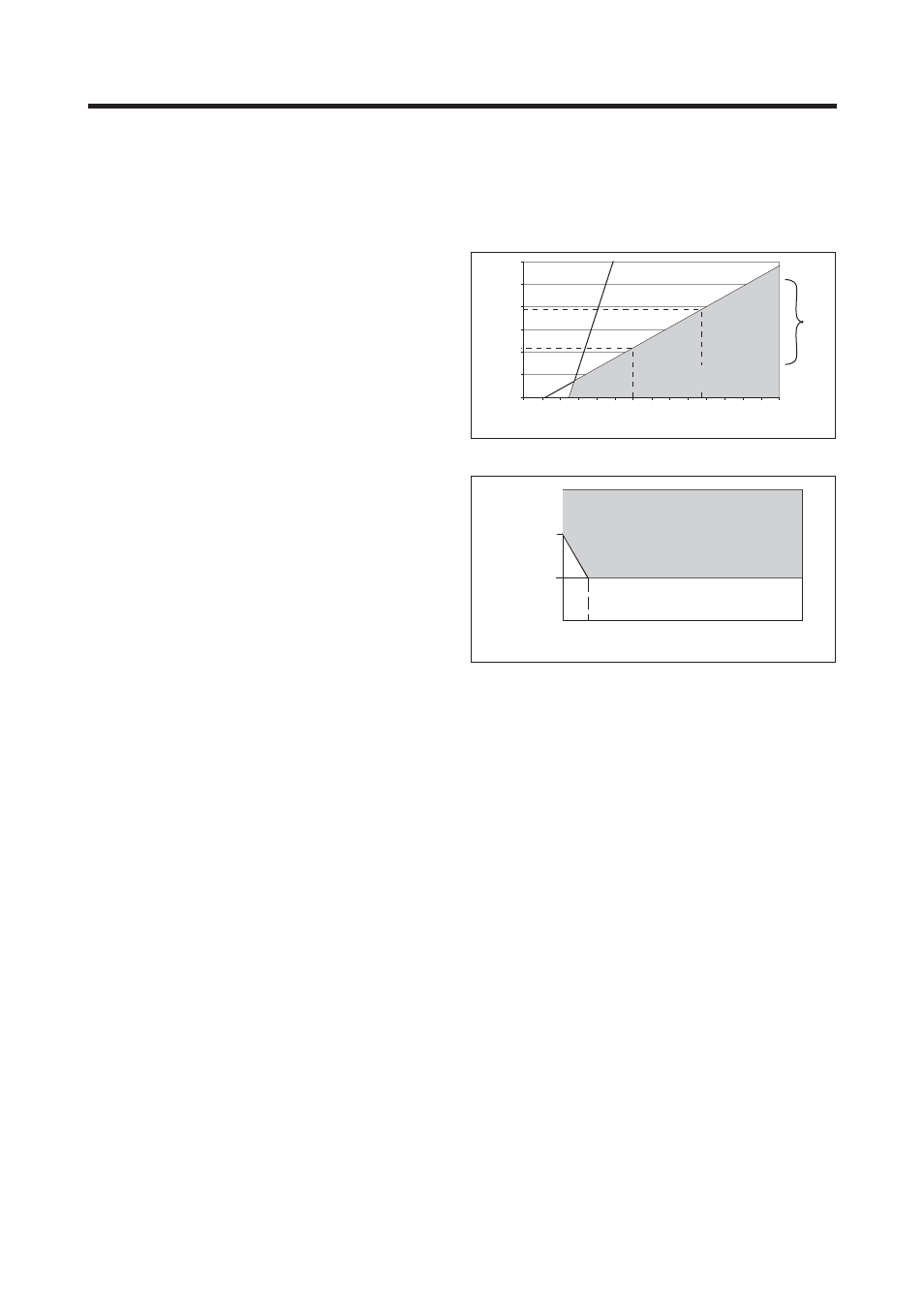
Note: The transmitter contains a switched
power supply. The transmitter requires a
minimum power voltage in order to work
correctly, which is dependant on the load.
Please refer to figures 2-1 and 2-2 for the
correct power supply
I. Input
isolation
1000 VDC
J. Shipping Details
Package size : W x H x D, 290 x 300 x 290
mm (11.5 x 11.8 x 11.5 inch)
Packed weight
: approx. 2.5 kg (5lb)
2. GENERAL SPECIFICATIONS
Figure 2-1. Supply voltage/ load diagram
Figure 2-2. Minimum terminal voltage at the DO202
0.0
200.0
400.0
600.0
800.0
1000.0
1200.0
4 mA
22 mA
425.0
775.0
31.5 V
(limit for IS version)
Load Resistance (
Ω
)
230.0
1100.0
Communication
Range
12 14 16 18 20 22 24 26 28 30 32 34 36 38 40
Voltage (V)
17 Volts
14.5 Volts
4 mA 7 mA
20 mA
Terminal voltage (V)
Output Current (mA)