Yokogawa DO202 2-Wire Dissolved Oxygen Analyzer User Manual
Page 22
IM 12J05C01-01E
2-11 General Specifications
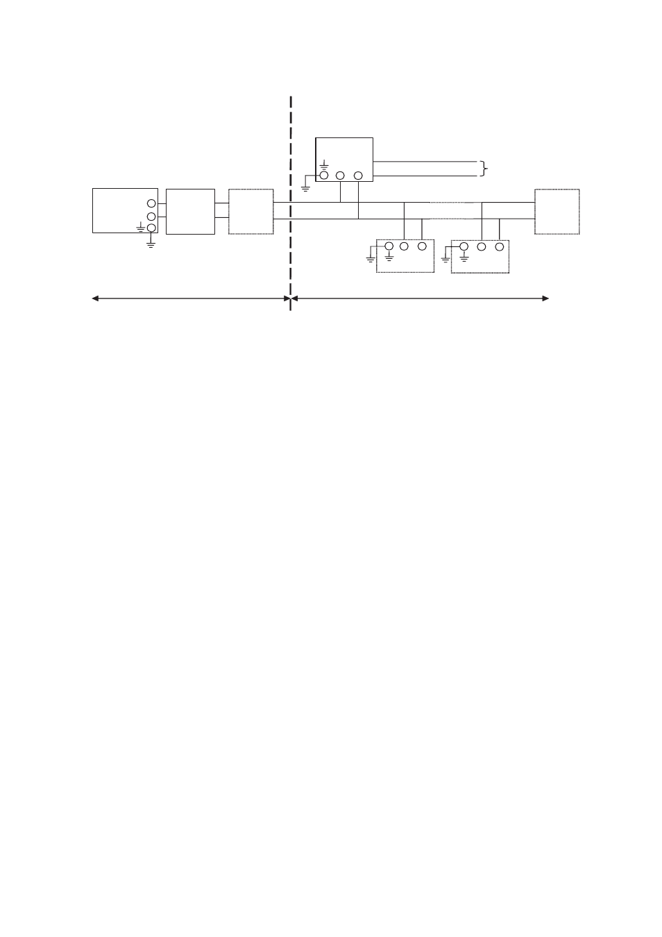
2-9. Control Drawing of DO202S FF/PB Specification (IECEx)
Safe area
Hazardous area
Zone 0 or 1
Safe area
Apparatus
I.S.
interface
I.S.
certified
Terminator
Ui = 24 V
or Ui = 17,5 V
Ii = 250 mA Ii = 380 mA
Pi = 1,2 W Pi = 5,32 W
Ex ia IIC
T4 for ambient temp. d 55 qC
DO202S-F
or DO202S-P
I.S.
certified
Terminator
-
+
-
+
Transmitter
Transmitter
Sensor
Connections
-
+
-
+
x
Sensor(s) are of a passive type to be regarded as 'simple apparatus'.
x
Electrical data of the DO202S-F & DO202S-P:
-
Supply
and
output
circuit:
Maximum input voltage Ui = 24 V
Maximum input current Ii = 250 mA
Maximum input power Pi = 1.2 W
Effective internal capacitance Ci = 220 pF;
Effective internal inductance Li = 0 μH.
or
FISCO field device
Maximum input voltage Ui = 17.5 V
Maximum input current Ii = 380 mA
Maximum input power Pi = 5.32 W
Effective internal capacitance Ci = 220 pF;
Effective internal inductance Li = 0 μH.
-
Sensor input circuit:
Maximum output voltage Uo = 14.4 V; Maximum output current Io = 22 mA
Maximum allowed external capacitance Co = 643 nF
Maximum allowed external inductance Lo = 70 mH
x
Any I.S. interface may be used that meets the following requirements:
Uo d 24 V
Io d 250 mA
Po d 1.2 W
Co t 220 pF + Ccable; Lo t 0 μH + Lcable
or
FISCO power supply
Uo d 17.5 V
Io d 380 mA
Po d 5.32 W
Co t 220 pF + Ccable; Lo t 0 μH + Lcable
x
Electrical data of the DO202S-B & DO202S-D (Type of protection “n”)
-
Supply
and
output
circuit:
Maximum input voltage Ui = 32 V
Effective internal capacitance Ci = 220pF; Effective internal inductance Li = 0 μH.
-
Sensor input circuit:
Maximum output voltage Uo = 14.4 V; Maximum output current Io = 22 mA
Maximum allowed external capacitance Co = 3.5PF
Maximum allowed external inductance Lo = 160 mH