23 <3 installation and wiring – Yokogawa In-Situ Gas Analyzer TDLS200 User Manual
Page 36
3-23
<3 INSTALLATION AND WIRING>
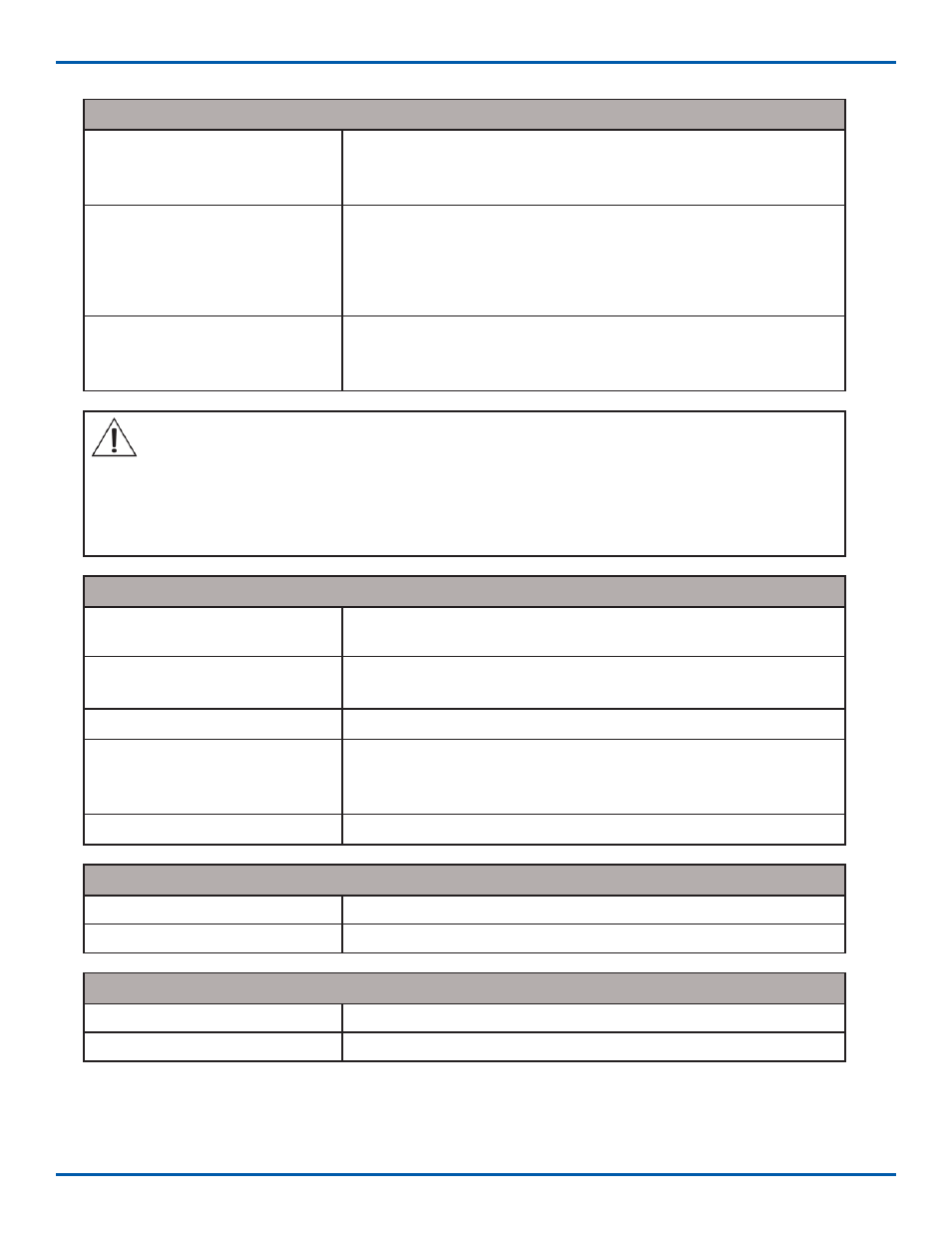
Normal Operating Conditions
Power
Certifi ed for installation and use in ATEX and IECEx for
Type Z – Purge, II 3 G Ex nA nL [pz] IIC T6
For Zone 2 gas hazardous areas
Manual Dilution Cycle Time To
Energizing Electrical Equipment
Typically, dilution cycle time is to ensure that at least fi ve (5)
times the volume of free space in the enclosure of protective
gas supply is exchanged before power is applied to the
electrical equipment. Ten (10) times volumes for motors,
generators and other rotating electrical machinery.
CYCLOPS Z – Purge Indicator,
Minimum Pressure
Green indicator light remains on to show purge pressure being
maintained above 0.20 inches H2O (0.50 mbar) in electronics
enclosure being monitored.
WARNING: The number of exchanged volumes may be higher in some situations. Refer to
TDLS-200 ATEX Purge Warning Labels for Details.
NOTE: Instrument Air and Nitrogen purge gases have different purge time requirement. It is
important to use clean, dry purge gases to ensure the pressure switch contacts do not foul and
cause subsequent operating issues (i.e. non-functionality of the Cyclops).
Utility Requirements
Purge Protective Gas Supply
Pressure to Pressure Regulator
20 psig (1.4 Bar) minimum (Suggested to compensate for
enclosure leak rate)
Purge Protective Gas Supply
Quality
Water and oil-free, - 40°F (- 40°C) dew point, particles ≤ 5μ, ISA
grade hydrocarbon free
Power Input / Consumption
0.5 Watts maximum
Voltage
CYCLOPS Z – Purge Indica-
tor
4VDC model (19VDC to 28VDC) 47 to 63 Hz
Mains Supply Fluctuation
Not to Exceed 10%
Environmental Conditions
Operating Temperature Range
- 40°F to 150°F (- 40°C to 65°C)
Used and Mounted
For Indoor and Outdoor Use
Casing Material Specifi cations
Anodized Aluminum Weight
2.48 lbs (1.13 kg)
Anodized Aluminum Protection
NEMA 4 (IP66)
IM 11Y01B02-11E-A 5th Edition :June 5, 2012-00