3 installation and wiring> 3-4 – Yokogawa In-Situ Gas Analyzer TDLS200 User Manual
Page 17
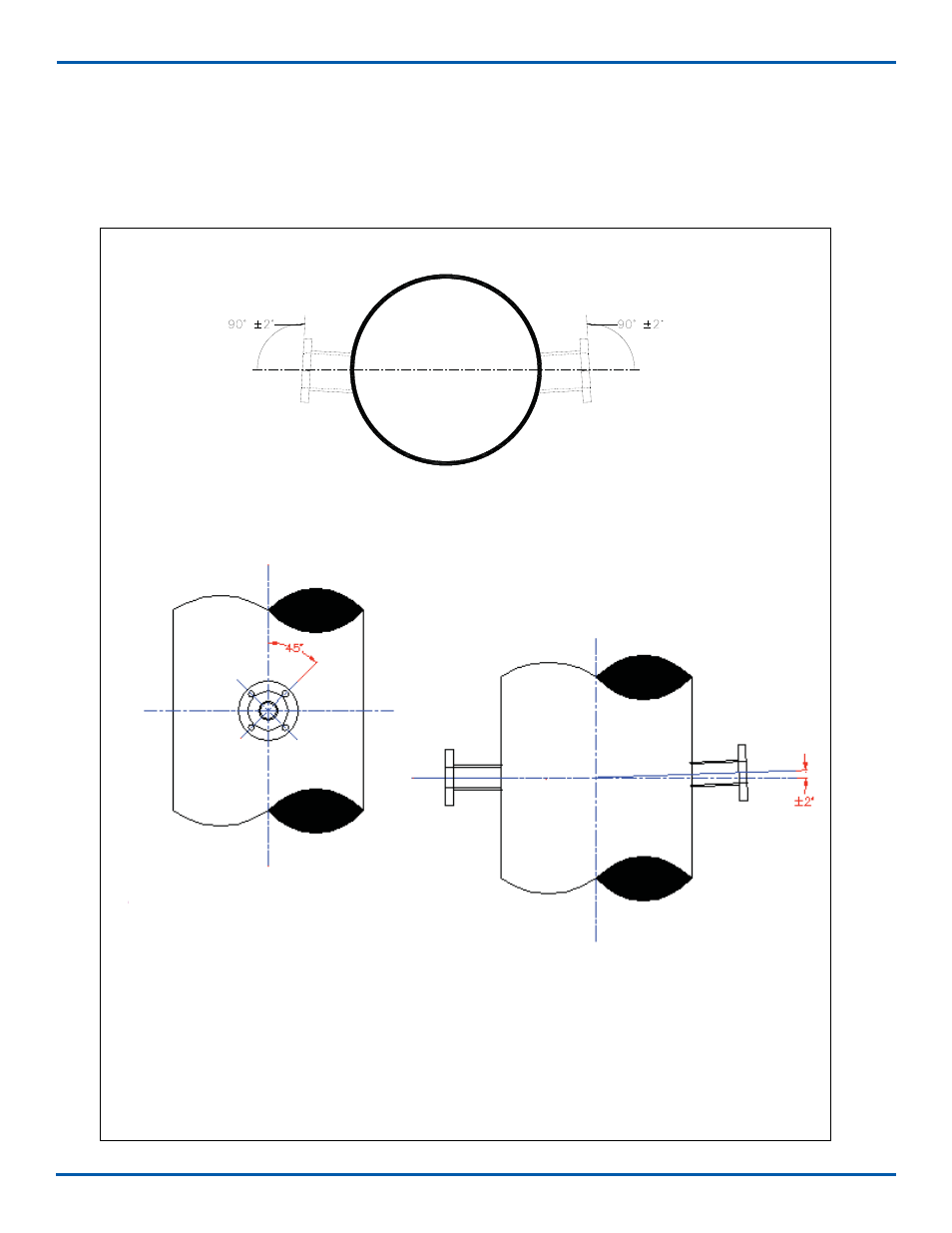
3.3 Process Flange Welding Alignment and Line-Up
The Launch and Detect units are provided with alignment mechanisms that allow for some manual adjustment
of the laser beam direction in both planes. It is however recommended that the following angular tolerances be
adhered to as closely as possible.
PROCESS FLANGE
BOLT ALIGNMENT
NOZZLE FLANGE BOLT PATTERN MUST BE AS
INDICATED TO ASSURE PROPER MOUNTING OF
ANALYZER LAUNCH AND DETECT UNITS
COMBINED ANGULAR OFFSET OF BOTH NOZZLES
MUST NOT EXCEED 2” IN ANY DIRECTION. BEST
INSTALLATION WILL HAVE NO ANGULAR OFFSET
PROCESS FLANGE
ANGULAR TOLERANCE
Angular tolerance
<3 INSTALLATION AND WIRING> 3-4
Figure 5 - Angular Alignment Tolerances for Launch or Detect Unit Flanges
IM 11Y01B02-11E-A 5th Edition :June 5, 2012-00