3 installation and wiring> 3-20 – Yokogawa In-Situ Gas Analyzer TDLS200 User Manual
Page 33
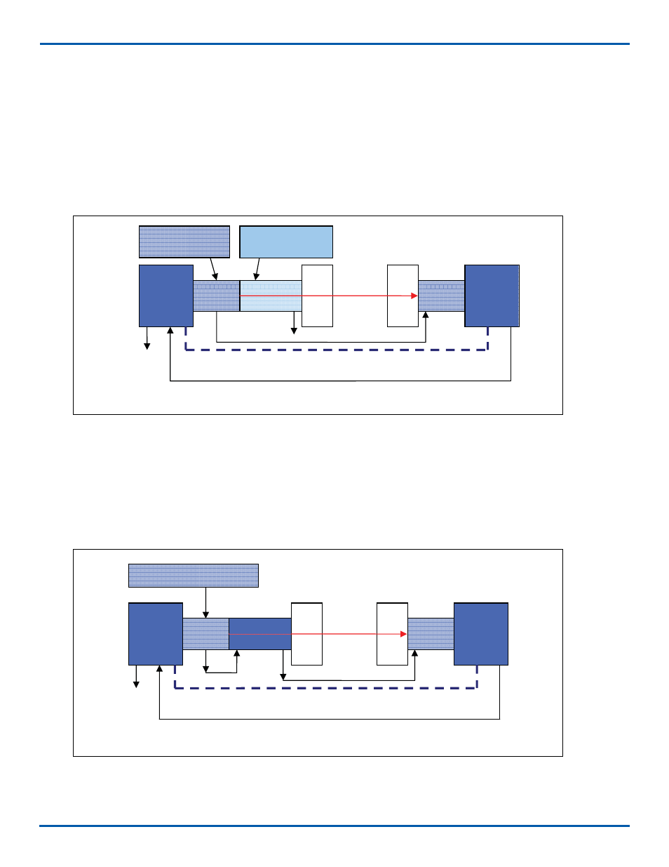
3.11.1 Purging Analyzer for Hazardous Areas (with On-Line Validation)
• NEC/CSA Class 1, Division 2, Groups A-D
•
ATEX Zone 2 CAT 3 Dual regulators must be used on the inlet!
The block diagram below shows the sections of the analyzer that require nitrogen purging. A Z-Type purge control
system is fi tted the Launch Unit and it includes a local indicator (Bright Green, rugged light) and pressure switch
alarm contacts (open on loss of purge pressure). The purging should be carried in sequence typically as shown
below. All purge gas connections are ¼” od Tube fi ttings.
3.11.2 Purging Analyzer for Hazardous Areas (without On-Line Validation)
• NEC/CSA Class 1, Division 2, Groups A-D
• ATEX Zone 2 CAT 3 – Dual regulators must be used on the inlet!
The block diagram below shows the sections of the analyzer that require nitrogen purging. A Z-Type purge
control system is fi tted the Launch Unit and it includes a local indicator (Bright Green, rugged light) and pres-
sure switch alarm contacts (open on loss of purge pressure).
Figure 26 - Purge Flow Diagram when not using on line validation
Main
Electronic
Housing &
Purge
System
Laser
Module
Check Gas
Flow Cell
P
roce
ss
Int
erf
a
c
e
P
roce
ss
Int
erf
a
c
e
Detect
Module
Detect
Electronic
Housing
Nitrogen or I/A Purge Gas
Main
Electric
Housing
& Purge
System
Detect
Electronic
Housing
Main
Electronic
Housing &
Purge
System
Laser
Module
Check Gas
Flow Cell
Proce
s
s
Inte
rfa
ce
Proce
s
s
Inte
rfa
ce
Detect
Module
Detect
Electronic
Housing
Nitrogen or I/A
Purge Gas
Nitrogen or I/A
Purge Gas
Figure 25 - Purge Flow Diagram when using on line validation
Main
Electric
Housing
& Purge
System
Detect
Electronic
Housing
Nitrogen or I/A Purge
Gas
Check Gas
Flow Cell
<3 INSTALLATION AND WIRING> 3-20
IM 11Y01B02-11E-A 5th Edition :June 5, 2012-00