Yokogawa ADMAG AXF User Manual
Page 61
IM 01E20C01-01E
6-32
6. PARAMETER DESCRIPTION
(4) The output signal becomes a damped curve and
compliance with the step signal begins.
Three seconds after determination of a flow rate
signal in the above figure, a level of 63.2% is
reached.
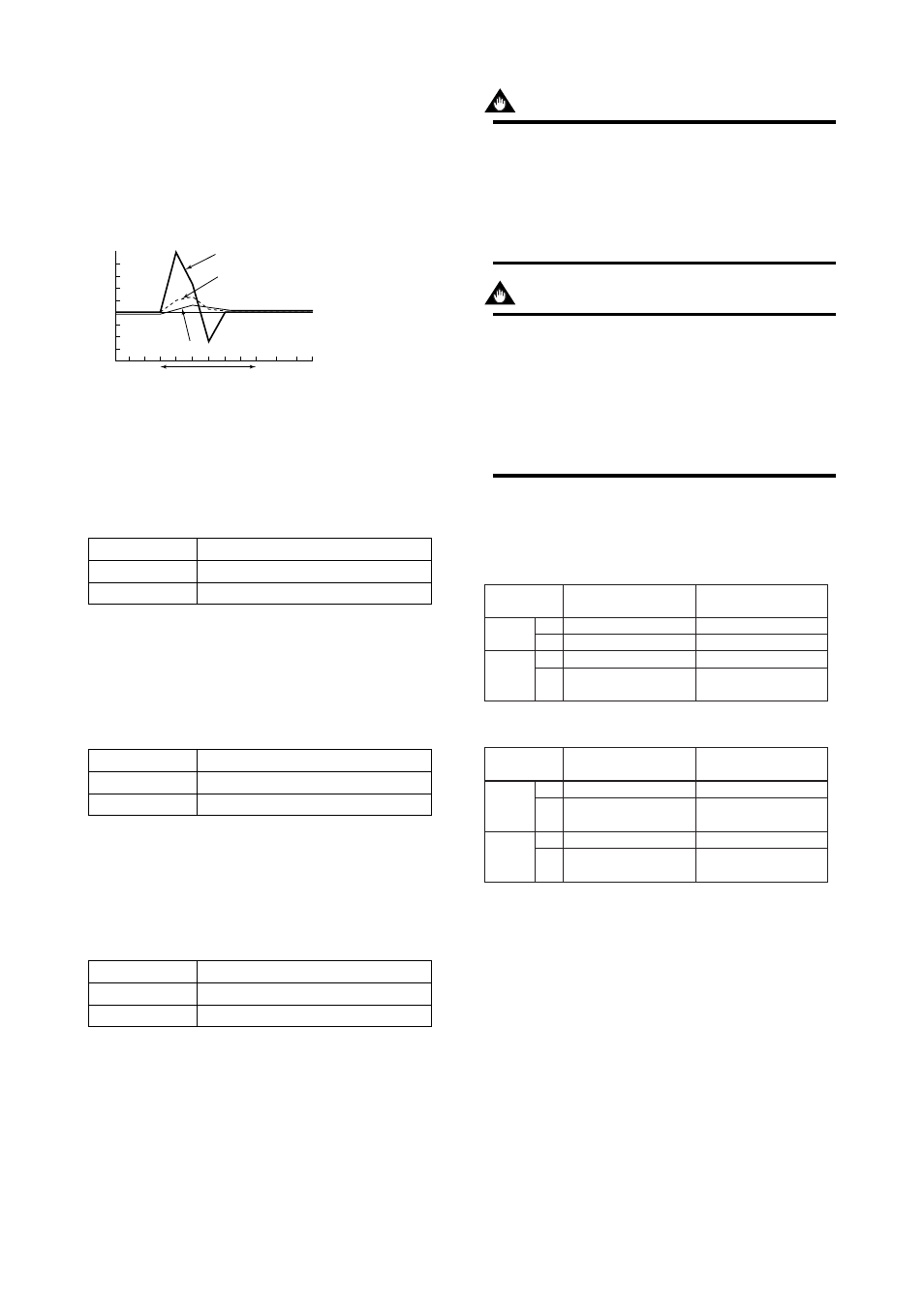
Example 2: Slurry noise
F0618.EPS
+1
%
-1
%
Dead time: 1 s
Flow rate value after damping
Flow rate value
after rate limit
processing
Slurry noise
Input: 0 to 10%
Damping time constant: 1 s
Dead time: 1 s
Rate limit value: 1%
Time
In the figure on the left, it is
determined that the slurries
noise signal is not a flow rate
signal.
[J23: Pulsing Flow] Selection of pulsing flow support
In a situation where pulsating flow causes error in the
average flow value, due to the application of a plunger
pump, this parameter provides functionality whereby
calculation is controlled and variations in flow rate are
followed.
Setting
Function
Normal
Support for pulsing flow
No
Yes
T0639.EPS
[J24: T/P Damp Select] Setting of damping operation
This parameter is used to select that the flow rate value
obtained through damping calculation for totalization
and pulse output or the instantaneous flow rate value
(no damping) for totalization and pulse output.
Setting
Function
Damping
No damping
Damp
No Damp
T0640.EPS
[J30: Power Synch] Setting of power synchroniza-
tion
This parameter sellects whether or not the internal
frequency is to be synchronized with that of the power
supply.
Setting
Function
Not synchronized
Synchronized
No
Yes
T0641.EPS
[J31: Power Frequency] Setting of power fre-
quency
When “Yes” (i.e., in synchrony) has been selected for
J30: Power Synch, this parameter is used to display
the power supply frequency. If “No” (i.e., not synchro-
nized) has been selected, the power supply frequency is
to be specified.
IMPORTANT
In situations where a DC power supply is used
for converters, set the local commercial power
frequency in area where the converter is in-
stalled (size 2.5mm to 1000mm). Set “No” for
J30: Power Synch and the local commercial
power frequency for J31: Power Frequency.
IMPORTANT
In situations where AXFA11 is combined with a
remote flowtube the size of 1100 mm (44 in.) to
2600 mm (104 in.), set the fixed frequency
(49.00 Hz) in case that either AC or DC power
supplies is used for converters.
Set “No” for J30: Power Synch and “49.00” for
J31: Power Frequency.
Following settings are necessary by power supply and
by flow tube size.
Power Supply Code 1
(100 to 240 V AC or 100 to 120 V DC)
T0642-1.EPS
J30
J31
J30
J31
Size 2.5 mm (0.1 in.)
to 1000 mm (40 in.)
Power synchronous (Yes)
No setting
Power asynchronous (No)
49.00 Hz
Power asynchronous (No)
Power asynchronous (No)
Local commercial power
frequency
49.00 Hz
AC power
supply
DC power
supply
Size 1100 mm (44 in.)
to 2600 mm (104 in.)
Power Supply Code 2 (24 V AC/DC)
T0642-2.EPS
J30
J31
J30
J31
Size 2.5 mm (0.1 in.)
to 1000 mm (40 in.)
Power asynchronous (No)
Local commercial power
frequency
Power asynchronous (No)
49.00 Hz
Power asynchronous (No)
Power asynchronous (No)
Local commercial power
frequency
49.00 Hz
AC power
supply
DC power
supply
Size 1100 mm (44 in.)
to 2600 mm (104 in.)
[J40: Memo 1] Setting of memo 1
[J41: Memo 2] Setting of memo 2
[J42: Memo 3] Setting of memo 3
These parameters are used with the memo function,
and up to 16 characters can be set for each.
[J50: Software Rev No] Display of software
revision
This parameter is used to display the software’s
revision number.