2 transducer block, Transducer block -4 – Yokogawa AXFA14G/C User Manual
Page 48
IM 01E20F02-01E
8-4
8. PARAMETER LISTS
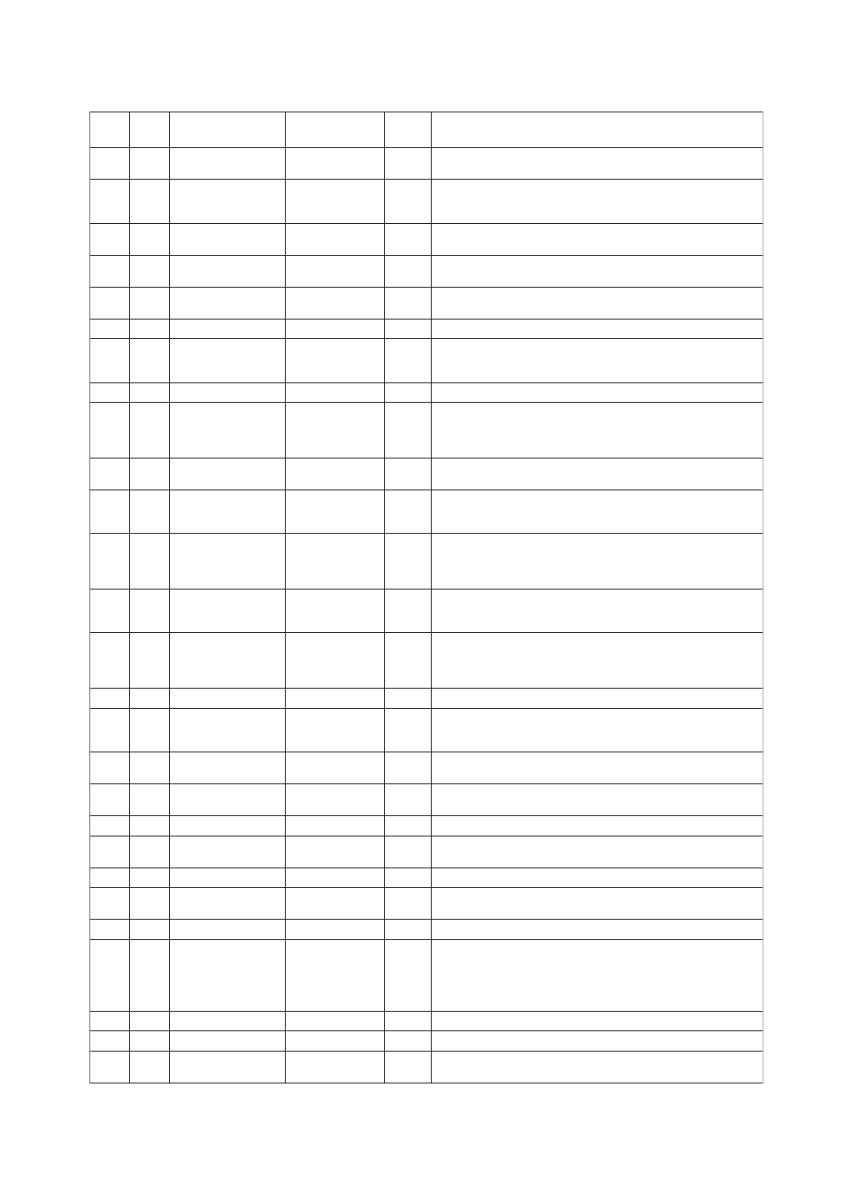
8.2
Transducer Block
T0802-1.EPS
Write
Mode
Explanation
Factory
Default
Relative
Index
Parameter Name
Index
Information on this block such as Block Tag, DD Revision,
Execution Time etc.
The revision level of the static data associated with the function
block. The revision value will be incremented each time a static
parameter value in the block is changed.
The user description of the intended application of the block.
The strategy field can be used to identify grouping of blocks.
This data is not checked or processed by the block.
The identification number of the plant unit. This information may
be used in the host for sorting alarms, etc.
The actual, target, permitted, and normal modes of the block.
This parameter reflects the error status associated with
hardware or software components associated with a block.
It is a bit string, so that multiple errors may be shown.
This alert is generated by any change to the static data.
The block alarm is used for all configuration, hardware,
connection failure or system problems in the block. The cause
of the alert is entered in the subcode field. The first alert to
become active will set the Active status in the Status attribute.
A directory that specifies the number and starting indices of the
device.
Identifies the device type, which is "Standard Flow with
Calibration" for the AXF.
Indicates the error code of the error of the highest priority from
among the errors currently occurring in the transducer block.
0=No failure, 20=Electronics failure, 21=Mechanical failure,
22=I/O failure
A directory that specifies the number, starting indices, and DD
Item IDs of the data collections in each transducer with a
transducer block.
The type of measurement represented by the primary value.
Followings are available for the AXF: 100: mass flow,
101: volumetric flow, 102: average mass flow, 103: average
volumetric flow
Indicates the flow rate.
Indicates the flow range. These values are converted the value
of SENSOR_RANGE by the unit of XD_SCALE and the data of
LINE_SIZE.
The highest calibrated value. To set within the range of
SENSOR_RANGE.
The lowest calibrated value. To set within the range of
SENSOR_RANGE.
The minimum calibration span value allowed.
The engineering unit for the calibrated values. Refer to Table in
5.4.1 for the units available.
Indicates the sensor type, which is "Electromagnetic" for the AXF.
The high and low range limit values, engineering units code and
the number of digits to the right of the decimal point for the sensor.
Serial number.
The method of the last sensor calibration.
100=volumetric
101=static weigh
102=dynamic weigh
255=other
Sets/indicates the location of the last sensor calibration.
Sets/indicates the date of the last sensor calibration.
Sets/indicates the name of the person responsible for the last
sensor calibration.
1 2001
ST_REV
0
3 2003
STRATEGY
1
4 2004
ALERT_KEY
1
Auto
5 2005
MODE_BLK
6 2006
BLOCK_ERR
0x0000
7 2007
UPDATE_EVT
8 2008
BLOCK_ALM
9 2009
10 2010
104:
Standard Flow with
Calibration
13 2013
O/S
14 2014
PRIMARY_VALUE
-
15 2015
16 2016
CAL_POINT_HI
2
O/S
17 2017
CAL_POINT_LO
0
O/S
18 2018
CAL_MIN_SPAN
0.1
22 2022
SENSOR_SN
Spaces
23 2023
101:
O/S
19 2019
CAL_UNIT
1061:m/s
O/S
20 2020
SENSOR_TYPE
102
O/S
21 2021
SENSOR_RANGE
24 2024
SENSOR_CAL_LOC Yokogawa
O/S
25 2025
SENSOR_CAL_DATE
0, 0, 0, 0, 0, 0
O/S
26 2026
SENSOR_CAL_WHO Yokogawa
O/S
11 2011
XD_ERROR
0
12 2012
2 2002
TAG_DESC
0 2000
BLOCK_HEADER
TRANSDUCER_
DIRECTORY
TRANSDUCER_
TYPE
COLLECTION_
DIRECTORY
PRIMARY_VALUE_
RANGE
PRIMARY_VALUE_
TYPE
SENSOR_CAL_
METHOD
101:Volumetric flow
32 space
characters
Auto
Static weigh