Yokogawa AXFA14G/C User Manual
Page 37
IM 01E20F02-01E
5-12
5. EXPLANATION OF BASIC ITEMS
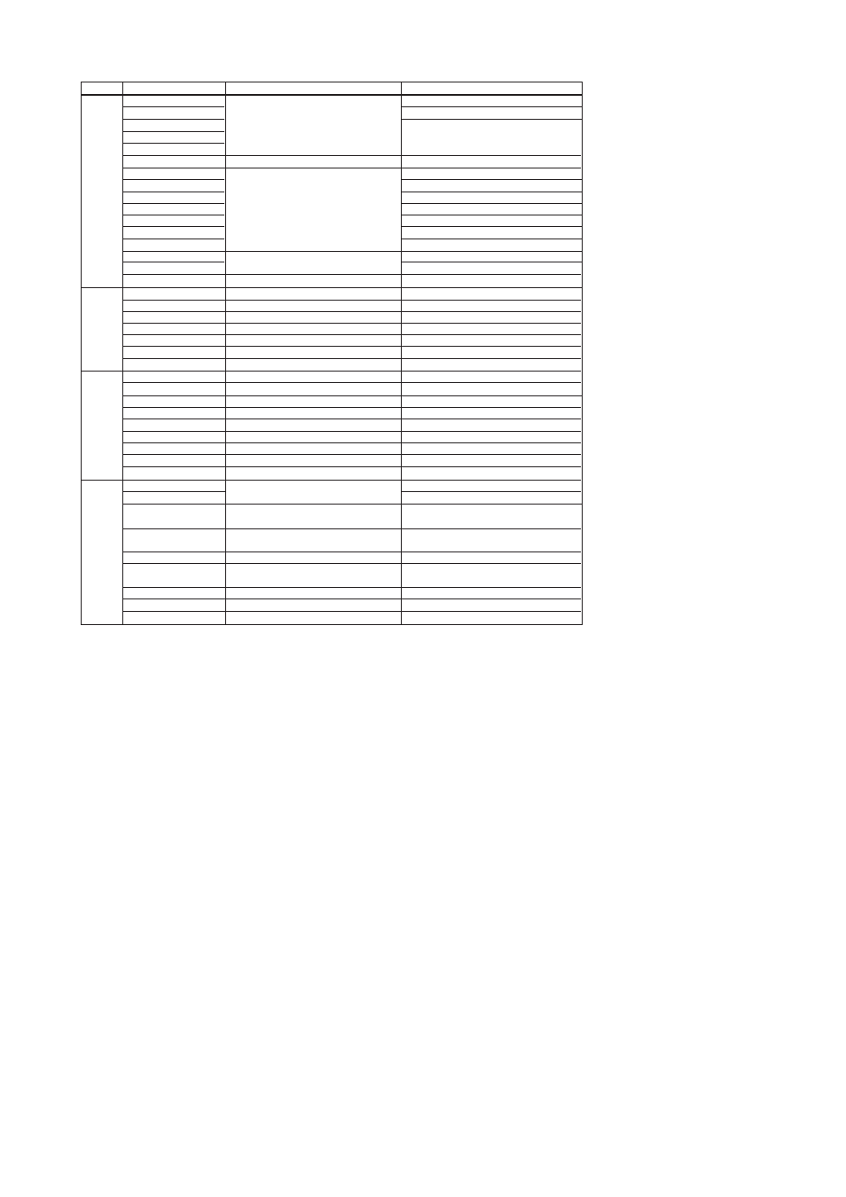
10:uP Fault
11:EEPROM Fault
12:A/D(H) Fault
13:A/D(L) Fault
14:A/D(Z) Fault
15:Coil Open
16:EEPROM Dflt
100:Comm uP Fault
101:Comm EEPROM Fault
102:IT1 Not Saved
103:IT2 Not Saved
104:Comm Error1
105:Comm Error2
106:DL Incomplete
107:Download Fail
108:Not Ready
30:Sig Overflow
31:Empty Pipe
33:Adhesion Alm
110:AI Lo Lo Alm
111:AI Hi Hi Alm
112:PID Lo Lo Alm
113:PID Hi Hi Alm
40:RS O/S Mode
41:TB O/S Mode
42:AI FB O/S Mode
43:IT1 FB O/S Mode
44:IT2 FB O/S Mode
45:DI1 FB O/S Mode
46:DI2 FB O/S Mode
47:AR FB O/S Mode
48:PID FB O/S Mode
50:Span > 10m/s
51:Span < 0.1m/s
72:Size Set Err
120:IT1 Clock Per Err
121:IT2 Clock Per Err
122:AR Range Set Err
Microprocessor (CPU) failure
EEPROM failure
A/D converter failure
Flowtube coil is open-circuit
EEPROM default values
Communication uP failure
Communication EEPROM failure
IT1 save error
IT2 save error
AXF internal communication error
AXF internal communication error
Download is not completed
Download failure
Function block not scheduled
Input signal error
Flowtube is not filled with fluid
Electrode adhesion alarm
AI process alarm
AI process alarm
PID process alarm
PID process alarm
RS. MODE_BLK.Target is O/S mode
TB. MODE_BLK.Target is O/S mode
AI. MODE_BLK.Target is O/S mode
IT1. MODE_BLK.Target is O/S mode
IT2. MODE_BLK.Target is O/S mode
DI1. MODE_BLK.Target is O/S mode
DI2. MODE_BLK.Target is O/S mode
AR. MODE_BLK.Target is O/S mode
PID. MODE_BLK.Target is O/S mode
Span flow velocity setting is 11 m/s or more
Span flow velocity setting is 0.05 m/s or less
Mass units have been selected for Base
Flow Unit but density is set to zero.
Measure Mode is set to Enhanced DF without
selecting an optional code HF1 or HF2.
A value of 3000.1 mm or more is set for Nominal Size.
The condition in Adhesion detection level,
Level:1 IT1 CLOCK_PER set value is smaller than excecution period IT2 CLOCK_PER set value is smaller than excecution period RANGE_HI>RANGE_LO is not satisfied Check XD Scale,Density Unit,Mass Flow Density Check Measure Mode of TB Check Nominal Size,Nominal Size Unit Check Adhesion Level1 to Adhesion Level 4 Check Clock Period,Period of Execution Check Clock Period,Period of Execution Check Range Hi and Range Lo of AR Check XD Scale of AI Schedule FB, or check LAS communication Check signal cable and grounding Fill flow tube with fluid Clean electrodes Check the flow rate and setting value Check the flow rate and setting value Check the setting value Check the setting value Check software download error code Cut the power and check coil & EX cables Contact nearest office or service center Contact nearest office or service center Category Category Alarm Message Alarm Message Countermeasure Message Countermeasure Message Alarm Description Alarm Description Process Alarms O/S Mode Alarms Setting System Alarms T0515.eps 73:Adh Set Err 71:Meas Mod Set 57:Dens Set Err Warning Display In each normal display one to three line display, when warning is generated, at the third line warning message is Data display.
Alarms
displayed. The following is the example of two line