2 zero point adjustment, Zero point adjustment -2, Important – Yokogawa EJA530E User Manual
Page 30
<7. Operation>
7-2
IM 01C25F01-01E
Using the integral indicator
• If the wiring system is faulty, the display stays
blank.
• If the transmitter is faulty, an error code is
displayed.
Self-diagnostic error on the integral indicator
(Faulty transmitter)
F0703.ai
Figure 7.3
Integral Indicator with Error Code
NOTE
If any of the above errors are indicated on
the display of the integral indicator or the
communicator, refer to subsection 8.5.3 for the
corrective action.
■ Verify and Change Transmitter Parameter
Setting and Values
The parameters related to the following items are
set at factory as specified in order.
• Calibration range
• Integral indicator display
• Software damping (optional)
Other parameters like following are shipped with the
default setting.
• Low-cut
• Process alarm setting
• Signal characterizer
• Write protection
To confirm or change the values, see IM 01C25T01-
06EN or 01C25T03-01E.
7.2 Zero Point Adjustment
After completing preparations for operating the
transmitter, adjust the zero point.
Zero point adjustment can be done by turning the
transmitter’s zero-adjustment screw or by using
the communicator. This section describes the
procedure for the zero-adjustment screw. For the
communicator procedure, see the communication
manual.
IMPORTANT
Do not turn off the power to the transmitter
immediately after performing a zero point
adjustment. Powering off within 30 seconds of
performing this procedure will return the zero
point to its previous setting.
NOTE
Before performing this adjustment, make sure
that the external zero adjustment function has
NOT been disabled by a parameter setting.
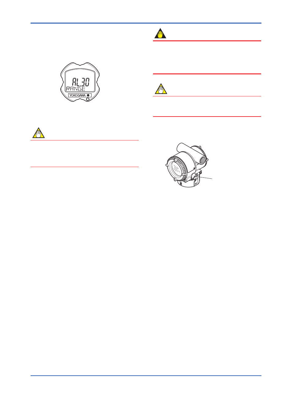
To check the output signal, use a digital multimeter,
calibrator, or communicator.
Zero-adjustment
screw cover
F0704.ai
Figure 7.4
External Zero-adjustment Screw
The zero-adjustment screw is located inside the
cover.
(1) When you can obtain the Low Range Value
from the actual measured value of 0% (0
kPa, atmospheric pressure);
For pressure measurement using gauge pressure
transmitters, follow the steps below before
performing zero point adjustment.
1) Close the tap valve (main valve).
2) Loosen the fill plug so that the pressure applied
to the transmitter is only the head of the seal
liquid.
3) Adjust the zero point at this status.
4) After the adjustment, close the fill plug and then
gradually open the tap valve.