Installation instructions - hydraulic models, Spreader operation - hydraulic models, Main components hydraulic plumbing diagram – SaltDogg 1400550SS / -H Self-Contained Hopper Spreader User Manual
Page 6
6
amount of material going into the spinner.
• Decreasing the engine RPM will decrease
the speed of the conveyor and therefore
amount of material going into the spinner.
• Opening or closing the feed gate door will
determine the amount of material dropping
onto the spinner for any conveyor speed.
Below are illustrations that show the baffles effect on
the spread pattern as viewed from the top of the spin-
ner disk.
Installation Instructions - Hydraulic Models
1. During assembly take precautions to keep all hy-
draulic components as clean as possible.
2. Allow enough hose length to prevent kinking and
stretching of the hoses and to permit raising the dump
body. Support long hoses with wire ties or clamps.
3. Protect hoses from wear caused by sliding and/or
vibration.
4. For proper rotation of conveyor chain and spinner
motors, hoses may be reversed. The spinner rotates
clockwise when looking down from the top.
Note: Use of a pipe joint sealant compatible with
hydraulic oil is recommended for all screw fittings.
5. Use swivel type hose ends to connect hoses to
flow valve. Damage to valve body may occur if the
fittings in flow valve are over tightened.
6. A 10 micron return line filter is recommended to
protect the pump, valve, and motors from wear caus-
ing contamination.
1
HV715
1
Dual Flow Regulator Valve
2
–
1
Reservoir 25 Gal Min
N/S
HVC1
1
Dual Flow Regulator Console
ITEM
PART NO.
QTY.
DESCRIPTION
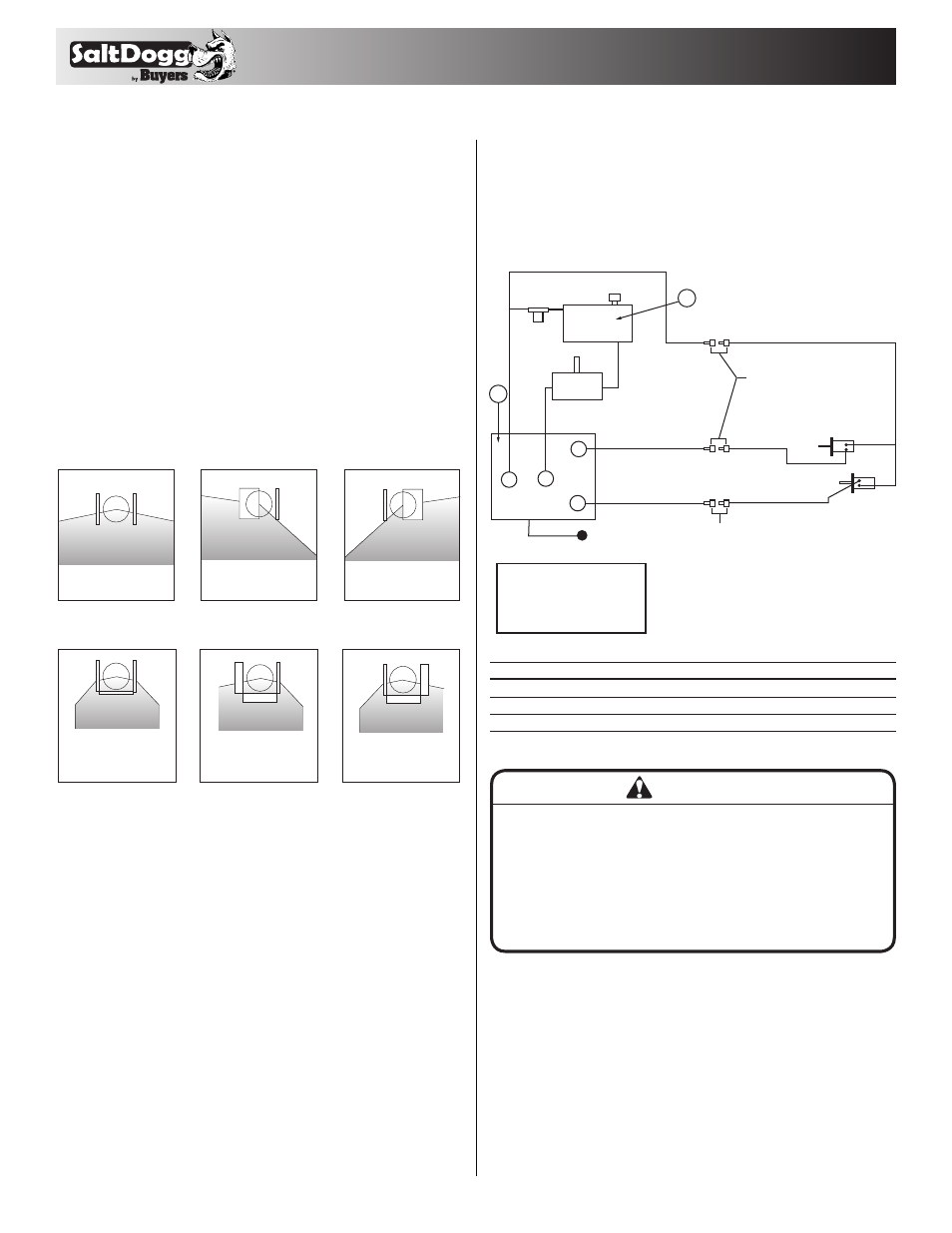
Main Components
Hydraulic Plumbing Diagram
ON/OFF Lever
1/2" Quick Disconnects
3/4" (1)
Wire Hose
3/4" (1) Wire Hose
1/2" (1) Wire Hose
1/2" (1) Wire Hose
1/2" (1) Wire Hose
Conveyer
Chain Motor
Spinner Motor
3/4" Quick
Disconnects
3/4" (2) Wire Hose
1-1/4" Spiral
Suction Hose
10 Mircon
Filter
3/4" (2) Wire Hose
1/2" (1) Wire Hose
Tank
Pump
Valve
2
T
A
P
S
Valve Key
T= Tank/Reservoir
P= Pump/Pressure In
A= Auger (Conveyer Chain)
S= Spinner
(1) Single braid wire hose
(2) Double braid wire hose
1
Spreader Operation - Hydraulic Models
Initial Priming and Inspecting of the System
1. Use high grade non-foaming hydraulic oil to fill res-
ervoir about 3/4 full.
2. Position valve on/off lever to off.
CAUTION
• Be sure everyone is standing clear of spreader.
• Be alert for anything that may require shutting
down the system.
• Before working in or around spreader equipment,
be sure all hydraulic controls are moved to off
position.
3. Move auger (conveyor chain) and spinner knobs on
the valve to the open position.
4. Engage PTO and circulate hydraulic oil for several
minutes to warm up.
5. Move valve on/off lever to on.
6. Inspect hydraulic system for leaks.
7. Check conveyor chain and spinner to see if they
are working properly and rotating the correct direc-
tion. To reverse rotation, switch the hydraulic lines at
the motor.
Both internal
baffles out
Left baffle in,
Right baffle out
Right baffle in,
Left baffle out
All baffles adjusted
down for a confined
spread pattern
Right baffle deflects
material down;
heavy on right side
Left baffle deflects
material down;
heavy on left side
Internal Baffle Adjustment
External Baffle Adjustment