General installation instructions – all models – SaltDogg 1400550SS / -H Self-Contained Hopper Spreader User Manual
Page 3
3
General Installation Instructions –
All Models
1. Mounting the Spreader onto the Vehicle:
• Remove the tailgate from the vehicle if applicable.
• Lift the spreader using the (4) lifting loops in the
corners of the hopper.
Control Box & Vehicle Wiring Harness Installation
- Gas Powered Models.
Note: The following instructions show how to
install the spreader so that the engine will draw
power to start the engine from a dedicated battery
located on the spreader.
1. Vehicle Wiring Installation
WARNING
The lifting device must be adequately rated to lift a
payload equal to or greater than the spreader weight.
See page 1 for spreader weights. Empty spreader
before lifting.
• Keeping the spreader elevated off the vehicle with
lumber helps with removal of material that accumu-
lates under the spreader during operation. Place
lumber under the side gussets and central rails of the
spreader.
• Center the spreader in the vehicle with the end of
the spreader about 14" beyond the back end of the
vehicle.
• Bolt the spreader through the lumber and into the
vehicle frame using the holes located in each of the
side gussets. Use 1/2" SAE grade 5 hardware.
• The spreader may be further secured to the vehicle
by using appropriate tie-down straps from the spread-
er to the vehicle’s factory installed anchor points.
• Verify with the vehicle’s manufacturer that the fac-
tory installed anchor points are designed for tie-down
of such load.
• Periodically check that the spreader mounting hard-
ware is securely tightened.
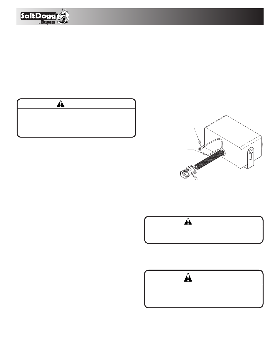
ATTACH TO
VEHICLE GROUND
ATTACH TO 12V DC POWER
SOURCE CONTROLLED
BY VEHICLE IGNITION
TO SPREADER HARNESS
Cab Control Box
• Determine a wiring path for the vehicle wiring har-
ness.
WARNING
Do not drill holes into fuel tanks, fuel lines, through
electrical wiring, etc that may be damaged by drilling.
• Mount the control box in a convenient location in the
truck cab.
WARNING
Do not install control box in the vehicle’s airbag
deployment area. Refer to the vehicle’s manual for
airbag deployment area.
• Connect the green wire from the vehicle wiring
harness to a known good vehicle ground.
• Connect the stripped end of the red wire to an
accessory wire terminal that is controlled by the
vehicle’s ignition switch.